Boring Falcos
![]()
Boring Falcos |
|
by Clive Garrard
This article appeared in the March 1998 Falco Builders Letter. |
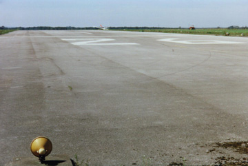
Skid marks on the runway where Clive tried to escape to the side.
Back in August last year, I had the misfortune to have an accident in G-OCAD, following a partial power loss on take off. The gear was still down, and there was runway left, so I landed again. However, the runway end was looming very rapidly and with a harvested field full of 6 ft diameter bales beyond, I steered towards an old perimeter track in an attempt to stop safely. Here (if I had any), my luck ran out completely and an unforeseen low concrete block knocked off the nose gear, followed by the inevitable destruction of the propeller, together with damage to the spinner and lower cowling. A second block sideswiped the starboard main gear leg-destroying the brake assembly and denting the disk.
Clive advises other Falco pilots to avoid these types of concrete blocks.
I have related the above facts, not in order to report the accident for any reason, but simply as a lead-in to two further items that may interest past and present builders of this superb aeroplane.
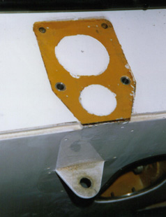
While we (David Nowill, Gordon Blunt and myself), were carrying out the repairs (which we were relieved to find were 99% confined to the metal components), we observed that the side load strut mount had been moved outwards at the bottom, by about 1-1.5mm. David and I discussed the problem, and we decided to slacken off the bolts, retract the gear and with the mount having realigned itself, retighten them. This appeared to be satisfactory, but after a couple of flights we noted that the mount had moved out of position again.
It was obvious then, that we had some damage that we had to investigate and repair, but with the annual due in a few weeks, we decided to resolve it at that time. During that period we mulled it over, and I stated my belief that the bolts must be bent and the holes in the main spar deformed-which would allow the position shift. David agreed with this theory, so I ordered a new set of nuts and bolts in anticipation, while we continued to discuss how we might effectively close up the damaged holes. At first, David thought about making a jig plate, through which we could drill larger holes, into which we could then insert some specially made bushes. While this would have positioned the holes accurately, it would not have aligned them, but at the time, that was our best shot at a solution.
Under the port wing, looking aft on the front of the spar.
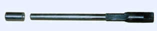
The annual date arrived and after dismantling the gear linkage, we removed the mount-which confirmed our damage theory completely. The two lower bolts were bent about 20mm from the head and the corresponding holes were ovalled. It was in the Aero Club bar, over a couple of beers, that (if I may say so), I had a flash of inspiration. I said to David, "What we really need is a boring tool that has a long mandrel at its front that will go right down the undamaged sections of the holes in the spar and which will, therefore, be self aligning." He, with great alacrity and vision knew exactly what was required-indeed, by the following day he had made the perfect tool, tested it in some oak and turned some aluminum bushes ready for the actual repair. The envisaged jig plate was not needed!
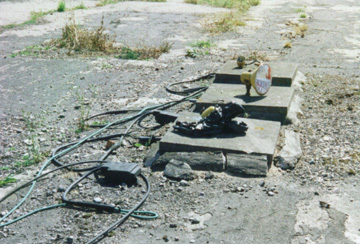
The spar boring tool and a bushing
When the tool was connected to a variety of universal joints and short extensions from a Snap-On socket set and powered by an electric drill, the boring was an absolute dream and only took seconds to perform. After insertion of the new bushes, the gear and links were reassembled and we were immensely gratified and relieved by the mount settling back exactly into the pre-accident position. If any builder finds himself with the same situation to resolve-the tool is available from us on loan-all he has to do is contact David or myself.
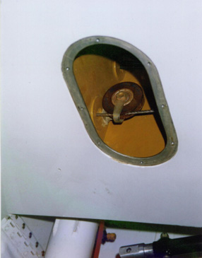
Under the starboard wing, looking forward showing
the removed bracket and the new bushings installed.
This now brings me to the second half of this story and some of you may have already deduced what is coming. How to get at the nuts at the front of the spar? There are no access panels built into the Falco at those points-although the construction manual does suggest they can be installed if desired, but no drawings support that notion. However, in our case, with the wing fully skinned and already an integral part of the fuselage, we discovered that the aileron cable forks would not pass through the pulley guards mounted on the inboard side of the wing ribs No 2. This rang alarm bells for the future-because what do you do when you eventually need to remove the cables for inspection/replacement? After much wailing and gnashing of teeth, we concluded that we sensibly had only one course of action and that was to attack the problem then, rather than later.
We determined from the drawings where the pulleys were and the size of hole that would be needed to gain working access. Of course, there was none of the normal framing already built in and the inside of the skins was fully varnished. We devised a scheme that involved an internal aluminum sub-plate, which could be fed through the hole once made and then secured in position. The access panel itself was made from aluminum the same thickness as the skin, so it automatically remained flush with the outer wing surface. Fitting the sub-plate meant scraping the varnish off the inside (not an easy job!), followed by bonding it into position with epoxy and backed up by countersunk machine screws. The screws are meant to be permanent and passed through the epoxy and were bedded into it. The heads were subsequently cleaned off flush with the wing surface and filled as necessary, before the final glass cloth was installed.
In addition to adding the panels, we made our own pulley guards-ones that were complete 'U's, rather than the specified 'L's. This system still keeps the cables completely trapped but allows free passage of the cable forks as and when necessary.
So by a remarkable piece of serendipity, we had exactly what was needed-access to the nuts previously mentioned. It was only after we had completed the repair that I realised the importance of those holes-making them now, in a completed/painted aeroplane, does not bear thinking about! I should add that this earlier modification to the wing was thoroughly investigated at the time by the PFA and approved by them. Again, if anyone needs more details-like the size and position for the openings-we will gladly supply them.
Contact me by telephone at 44 (0) 1858 545423, email at clive_beth@msn.com or David Nowill by telephone at 44 (0) 116 2593215.
![]()