A Canopy Caper
![]()
A Canopy Caper |
|
by John Brooks Devoe
|
This article appeared in the March 1992 Falco Builders Letter. |
John Devoe
Shortly after my canopy arrived, I called the old master and pastry baker in Connecticut for some guidance. At some point in the conversation, I am certain I heard the words "piece of cake" from Jim DeAngelo. In retrospect, I must believe he was talking about something he had just taken from the oven.
I re-read all the articles in the Builders Letter, checked in with Bob Bready, consulted the manufacturer of the plexiglas, clarified some matters with respect to the aft sliding tube with Alfred, and then began yet another learning curve. What follows is the sequence that evolved.
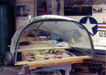
I began by fitting the frame to the fuselage with all its associated hardware-time consuming but not difficult-and then after ensuring that it slid well and true, I put additional primer on the frame and applied the final finish. Next I carefully measured the distance between the two forward sets of bolts/nuts and repeated the distance on a board which was fixed to a table somewhat narrower than the canopy, an overhang of some eight to ten inches on either side. The board's total length was some few millimeters shorter than the outer width of the canopy frame. Another board was prepared to be fixed to the table at the aft end of the canopy frame at the point at which the aft rollers are located in the canopy closed position. The length of this board also was short in length by a few millimeters of the canopy frame width at that point. No screws here, I glued two blocks to the board in a position that would be just inboard of the inboard side of the side rains. Thus the canopy would sit firmly and safely to the table (see photo).
I totally removed the protective covering from the plexiglas for a distance of about three inches from the rough-to be trimmed later-edges all around. I mounted the bubble on the frame favoring a forward position with sufficient overhang to provide for later trimming-in my case, it was not. This initial position should be done with the rubber weatherstrip installed, it should be in place when you drill, for it creates a different circumference than would the plexiglas alone against the frame.
And now the moment of truth, drill the holes. I remembered a caution given me by Jim: "Any time you're working with the canopy and especially when you are drilling, keep the temperature in the shop at at least 70° F." I cranked up the radiant heat panels. I drilled the first hole center top front and then went to the aft end, made sure things were aligned with equal overhang at each side and drilled a center-aft hole. I then drilled holes to the right and left of the first hole drilled at the forward end. I did not then go to the aft end but continued at the front, working my way down perhaps two holes at a time on each side and similarly along the sides towards the end of the canopy, and then up around the skirt area.
I used three drills for the process that worked for me. Two plexiglas drills (5/32" & 3/16") and one normally pointed drill( #40). The use of two plexiglas drills may not have been required, but it put me somewhat at ease for a reason I cannot readily recall. The first drill went through the 'glas, rubber and marked the steel of the frame. I then moved the weatherstrip away, placed small pieces of plywood on either side of the hole to create a space equal to the rubber and drilled with the larger drill, again using enough pressure to ensure a good mark on the steel. I next drilled through the steel with the third drill and installed the round head sheet metal screw, sometimes having to encourage it with a small vise-grip clamped to the head of a 'tool' screw of the same size. It is important to have an expansion space around all of these screws, and the method I used provided this in most cases. In the few times when it did not-observed during final assembly-I used a very small grinder in my Dremel tool to elongate as seemed necessary. I took the further precaution of countersinking, to a very slight degree, both sides of all holes before final installation.
At the half-way point, I returned the canopy to the fuselage to check for alignment and found no evidence of any problems.
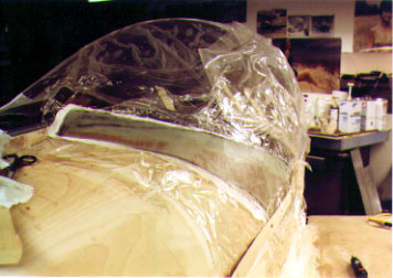
After reading Steve Wilkinson's description of an aluminum trim/skirt approach, I cowardly decided on that other composite, fiberglass. I also checked out on the minimum pieces approach and made mine in six sections, leading edge of canopy (2), sides (2), skirt (2) and a small far-aft section. This results in overlaps as can be seen in the photographs but for the purist, these could be joined at a later point in the process and reduced to perhaps a total of two pieces. I used six layers of 6-oz glass.
With the canopy back on the table, I replaced all the round-head screws with flat head phillips and gently screwed them in until they were flush with the plexiglas. I covered the edges with freezer wrap in a sufficient width to more than cover the width of the layed up glass. With this in place, I started laying up the glass, letting each two layers dry before adding the next two. While the glass was still not completely dry, I took an awl and pressed it into the glass at the center of the screw head, making a depression that would allow me to locate and drill the holes thorough the trim/skirt after it all was dry. On the front and sides, I then trimmed both the plexiglas and the trim and trimmed the plexiglas at the skirt area.
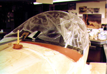
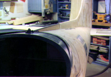
The canopy went back on the aircraft for the building of the skirt. This deals with the art of sculpture, and there are two kinds, additive and subtractive. That other Italian genius, Michelangelo, believe in the latter. He just cut away the waste marble and come up with the Pieta. I learned nearly a half century ago in a college sculpture studio that additive sculpture was a lot easier. Thus, rather than go through the foam round, I followed Bob Bready's lead and bought a dozen 4 oz sticks of Permoplast sculpture material-warm it and it is more easily worked-and formed that compound curve required to join the curve of the fuselage with the unlike curve of the canopy frame (see photo). I covered this with freezer wrap and proceeded much in the same manner as previously described. One of those multiple-pin contour guides was helpful in assuring that both sides of the skirt have a similar shape. I had to make a spruce wedge-like affair as a spacer at the aft end of the canopy to fit between the plexiglas and the canopy frame. When it came to the interior weatherstrip, I had to build a ramp-like affair to insure the weatherstrip was high enough on the fuselage to provide a good seal. Be sure to clamp the canopy, weatherstrip installed, to frame four during the building of the skirt. The frame should be clamped/braced to retain it in the 90° (standard canopy) positon. Trim everything and the piece of cake is complete.
I countersunk the holes in the fiberglass trim/skirt and used tinnerman washers beneath the screws. It had been my intention ot use flat head phillips screws, but ended up using the round heads that came with the kit, finding the end result, oddly enough-more pleasing to the eye.
The most valuable advice I can give is to be patient, the most valuable tool a cordless electric screwdriver. You will remove and install those screws more times than I care to remember!
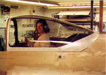
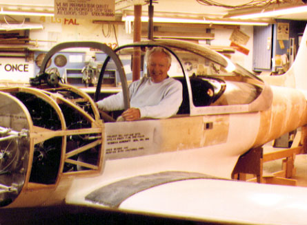
Gwen models the final product with a thumbs-up, but fortunately no one
retracted the gear. Note the Canadian turn signals on the side of the fuselage.
![]()