Notes & Comments
Electrical
![]()
Notes & Comments
|
|
|
From "Construction Notes" Falco Builders Letter, March 2004 |
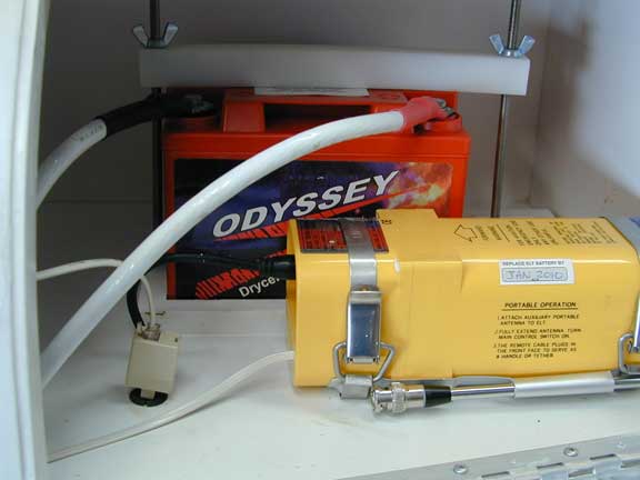
George Richards installed an Odyssey 925 battery, which he says gives amazing cranking power to his Falco. This is a sealed dry-cell battery. It is very small and saves 6 lbs over a Gill 25. He says "The chopper guys love them, and they regularly use them on a 320. I'm sure a 360 would be no problem. I've put the bigger 925 in. It is a great battery. Very compact, won't spill, has heaps of cranking power and doesn't seem to go flat as much if left alone. A great product." For more information, visit www.oddysseybatteries.com and check out the aircraft batteries.
|
From "Construction Notes" Falco Builders Letter, March 2004 |
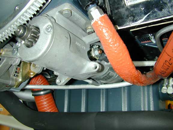
George also reports, "I've got the new Skytec High-Torque
Inline (NL model) starter in my Falco. (In fact I badgered Rich
at Skytec to give me the first one before they officially shipped!)
That combined with an Odyssey 925 battery gives amazing cranking
power to my 320. It is the best starter I've ever used, and it
fits the Falco great." Visit www.skytecair.com for full
details of this new starter. This appears to be a great starter
for the Falco since it doesn't require any changes to the baffling,
oil cooler installation or cowling. That's very good news.
|
From "Construction Notes" Falco Builders Letter, June 1997 |
Stephen Friend faxes, "It might seem a little late to be asking this question but is the wiring diagram for the marker high/off/low switch and resistor value correct? I have an RST marker and appear to be getting power only in the 'high' position."
As far as we know, the drawings are all correct. The intent of the resistor is simply to dim the lights at night. Nothing more. The dimmed lights are something you cannot easily see in daylight at all, so you'll need to test this in darkness.
|
From "Construction Notes" Falco Builders Letter, December 1996 |
Larry Black points out that you have a 'hot prop' when the instrument panel is removed. Hmmm, I guess I never thought about that before, but it's something to keep in mind since the engine could start if you pulled the prop through in that condition. Larry suggests disconnecting the spark plug wires when you have the instrument panel out.
|
From "Construction Notes" Falco Builders Letter, June 1995 |
Stephen Friend said that his mechanic noticed that his ignition switch was not hooked up correctly, with the result that the right magneto is not grounded when the starter is activated. In our wiring diagram, we show that the R terminal is grounded when the switch is in the 'start' position, however I had always assumed that this was an internal link. Apparently it is not.
The diagram for the switch shows eight terminals, while the switch actually has nine. There is an extra, unmarked terminal beside the R terminal that is grounded in the 'start' position. In addition, I note that the package for the switch includes a two-hole link that is apparently provided for this purpose. In checking the switches we have on the shelf, it is apparent that the R terminal is not grounded in the 'start' position and therefore must be linked to the adjacent, unmarked terminal to operate as it should.
|
From "Construction Notes" Falco Builders Letter, March 1994 |
In our electrical kits, we've recommended the AMP 601827-1 wire stripper. This model is a standard type that's used in radio shops by every technician. Recently we tried to order some tools from AMP for an overseas builder and some of them were discontinued-though Brenda doesn't remember which those were. In a catalogue, I noticed that Grainger is now selling a wire striper which appears to be the exact same model as the Greenlee 45000 (Grainger 5C655) for about $25.00.
|
From "Construction Notes" Falco Builders Letter, March 1994 |
Steve Wilkinson has been fighting a noise
problem with his strobes.
On the ground, when he is taxiing out, there is this whee-whee-whee
sound on the radios from the strobes-the sound that the last little
piggie made all the way home. In the air, the sound is less noticeable,
but Steve still wonders if it is affecting his range reception.
In casting about for an answer, Steve heard from John Schwaner who owns the famous Sky Ranch overhaul shop in California. John's advice to Steve was "Yes, there is a simple 100% cure. Install a choke (not a capacitor filter) on the power lead as close as possible to the strobe. The best type of choke is a wire-wound ferrite that Radio Shack sells. Next best are ferrite beeds, which have an advantage for certified aircraft in that the beads are external to the wire installation and probably don't require any approvals to use. Installation tips for strobes: 1. Don't run ac currents through the aircraft structure where they can radiate, i.e. don't use the aircraft as a ground circuit. Run the ground wire back with the power lead. 2. Best wire is a shielded 2-conductor but be careful. Shielding can radiate. Shielding should be copper (not stainless). Ground the shielding at both ends and at least every 10 feet. 3. For the frequency you are working with, the bus is not a low-impedence connection. Anything over .01 ohm is not low-impedence. The best place to connect is direct to the battery. The farther away, the more the problem you might have. When hooking to the bus, keep the connection as far away from the radio connection as you can. 4. Put another ferrite bead on the radio power lead. 5. This takes care of strobe whine. It does nothing for the strobe 'pop'. The whine is conducted primarily through the power lead; the pop is transmitted out of the top of the strobe. I have a simple ferrite bead kit for strobes if you are interested. I don't have the Radio Shack part number for the choke, but it looks like an internal transistor radio antenna-a couple of inches long with about 50 wraps of copper wire. Put it in series to the strobe as close to the strobe as possible"
Steve tried this on the two wing tip strobes (but not the tail strobe) and he hasn't yet gotten rid of the sound. At one point Steve thought he had the problem solved when he noticed that the radio that was hooked up to the antenna in the vertical tail was the only one that produced the whining sound. We concluded that the strobe leads are probably next to the antenna wire. That test was in the hangar and after taking the airplane out of the hangar, the problem persists. Lord knows why it would behave in the hangar and not outside the hangar, but there you have it. The mystery is still unsolved. More on this saga as it unfolds, but in the meantime we'd love to hear from anyone else who has solved this problem.
|
From "Construction Notes" Falco Builders Letter, December 1994 |
Steve Wilkinson has spent a lot of time recently chasing down some electrical problems with his Falco. There was a fluctuating-voltage problem, and also he has been plagued with the whee-whee-whee alternator noise problem.
It's been my observation that when people encounter electrical problems, they tend to behave in much the same way that people behave around computers when things start to go wrong. Something is clearly wrong, they can see the symptoms, but can't identify the cause, so they thrash about trying various solutions until something works.
Steve will certainly admit that this happened to him. He took Light Plane Maintenance editor John Likakis for a ride in the Falco, and John said the problem looked familiar and that Steve needed an alternator noise filter. None was installed on the plane, so Steve ordered one and pronounced the problem nearly solved. I was skeptical and thought that it was premature to consider the problem solved until he could confirm it. The filter arrived, and it didn't do a thing to help the problem. Ha!
Steve made contact with Robert Nuckolls, a former Cessna and Piaggio-Wichita electrical engineer, and a regular on the Compuserve Aviation SIG. Nuckolls is an active EAAer who now makes a living writing articles for Sport Aviation and Aviation Consumer and publishing "The AeroElectric Connection", a huge tome on electrical system design and installation directed at homebuilders.
I'm always skeptical about people who pop up in homebuilding and announce themselves as experts. There are plenty of true experts out there, and also large quantities of blowhards, but one look through "The AeroElectric Connection" is convincing proof that Nuckolls knows his stuff. It's a superb book, largely intended for homebuilders who are designing an electrical system, but Steve says "There's a lot in it that I wish I'd known-or simply understood better-when I was assembling my system."
If you're interested in getting a copy, "The AeroElectric Connection" is available for $42.00 and additionally there is a $12.00/year subscription for updates to the book and a newsletter. These become appendicies to the book. Orders may be placed by telephone to (316) 685-8617, Compuserve e-mail at 72770,552 or to Medicine River Press, Inc., 6936 Bainbridge Road, Wichita, KS 67226-1008. Visa/Mastercard accepted.
Based on reading this book and corresponding with Nuckolls, Steve decided that the problem probably lay with the voltage regulator and thus embarked on his second pot of Fool's Gold. Nothing wrong the the new regulator-it worked just fine, and may well be a better regulator-but the fluctuating voltage problem persisted! This is intentional. God meant electricity to be frustrating-just look it up in the Bible.
In the end, Steve solved the problem by simply popping the alternator-field circuit breaker and resetting it. The voltmeter is now dead-steady, and Steve thinks that all of the whee-whee-whee noises in the audio system are gone as well.
|
From "Construction Notes" Falco Builders Letter, March 1993 |
For years now we have been standardized on using the David Clark Isocom, however this model is being phased out of production, and it appears we bought the last one in existance for Stephen Friend. I have talked to the David Clark Company and they have no plans for a replacement that will fit in a 2-1/4" hole.
Unless anyone has any better idea, I think we will standardize on the Sigtronics SPA-400 intercom from now on. It's a popular, reasonably priced intercom that you can order with an optional face-plate so the intercom will fit in the 2-1/4" hole in our panel. Sigtronics is sending us wiring diagrams, and I'll modify our electrical drawing to accommodate this intercom.
|
From "Construction Notes" Falco Builders Letter, June 1993 |
Steve Wilkinson points out that if you're shopping for a used Century I autopilot for the Falco, the model that we use was also used in a Cherokee Arrow. We've always told people that you want the one from a Yankee, but Steve found that the Pipers used the same thing and that they're far more plentiful in salvage yards.
|
From "Construction Notes" Falco Builders Letter, September 1993 |
Sky-Tec also sells the Concord sealed recombinant-gas battery. This is a sealed 25 amp, 12 volt battery that is suitable for use in aerobatic aircraft. The battery sells for about $120.00. Tom Williams said the battery would have about the same 4-5 year life span as a Sears battery and would last about as long as a normal aircraft battery-possibly a little longer because the plates can't warp. Tom Williams spits at Gel-Cells and says that if you get two years out of a Gel-Cell, you're lucky. That's something I've heard from many other people.
|
From "Construction Notes" Falco Builders Letter, December 1993 |
From an article in Light Plane Maintenance, Steve Wilkinson learned that a GE H7604 halogen bulb is a direct interchange for the conventional GE landing light bulb we use, and that owners of many other light planes have switched without "no diminution in lighting effectiveness" and claim fewer problems with broken filaments.
Landing light bulbs are rather notorious for failing just when you need them. Some people swear that putting the bulb in with the filament vertical will solve the problem, but Steve says that the landing light in his Falco has never worked when he needed it.
Steve reports, "The halogen landing light bulb is available in any good automotive-parts store, since they're commonly used by people who affect those big light-bars atop their pseudo-offroad pickup trucks. They're made by a number of manufacturers and all bear the same GE part number, H7604. Retail price is $34, typical parts-store discount price is $20. The terminals on the back of the bulb are identical to the ones on the back of the standard incandescent bulb. The halogen bulb does have a conventional-looking filament, inside a bulb-within-a-bulb, but apparently it's beefier than the one in the incandescent bulb. The bulb is rated at 10,000 candlepower and has an operating life of 100 hours-lit, I assume."
|
From "Construction Notes" Falco Builders Letter, June 1992 |
Somebody asked in the last builder letter about grounding
metal parts in the airplane and what sort of wire to use.
I mentioned that any wire could be used. This caused Steve Wilkinson
to mention that Aircraft Spruce already sells a wire specifically
made for this purpose. It's called 'tinned copper braid' and it's
a flat thing that looks like a metal shoe lace. It's nice because
since it's flat and braided, you can staple it in place if you
like, and if you want to attach it to a bolt and continue on,
it's just a matter of driving an ice pick through it to create
a hole for the bolt.
|
From "Construction Notes" Falco Builders Letter, June 1992 |
Jerry Walker mentioned that the accelerometer that IFR now supplies has a bezel that 3mm over the 2-1/4" hole. I spoke to IFR's Jim Garufo about these made-in-China instruments. He said he went to China and took along a bunch of drawing of how U.S. instruments are made. The company he dealt with has been making instruments for years, but not for the U.S. market. In return for his services, IFR got exclusive world marketing rights. It also appears that the Chinese company substituted a few parts and this results in a slightly oversized bezel on the gauge.
Jerry Walker said that he would recommend that you not attempt to enlarge the hole in the panel or to cut the panel out for the rather odd-shaped thing-thing about the knob in the lower left. Instead, he said if he had to do it all over again, he'd just use longer screws and pull it up snug to the back of the panel.
|
From "Construction Notes" Falco Builders Letter, March 1991 |
Steve Wilkinson and Howard Benham are both working on installing a split bus so that they can have a separate avionics master switch. What you do is saw the bus bar in half at the avionics circuit breakers and then use a 'switch' to connect the two. There are two methods for doing this. By far the simplest is to use a 35 amp switch-type circuit breaker and some 8 gauge wire. That's the way Jim DeAngelo did it on his Falco, and my Falco has the same scheme.
The other method is to use a switch and a relay. That's what Beech does on all their planes, and Howard Benham is copying their system. You use a Cutler-Hammer 6041H53A relay and run the wires from each bus to the B1 and B2 terminals of the relay. That relay is a double-throw relay and by using the B1 and B2 terminals you are using the normally-closed terminals. This makes the system fail-safe because you apply power to the relay to turn the avionics bus off, thus any failure in the power to the relay coil restores power to the avionics bus.
|
From "Construction Notes" Falco Builders Letter, March 1991 |
Jim Petty also points out that the instrument post lights have hollow brass stems, and that it is very easy to break the lights by tightening the nut too tight. Many Falco builders have broken at least one post light this way. You only need to tighten the nut a little more than finger tight.
|
From "Construction Notes" Falco Builders Letter, September 1991 |
I've been getting some reports that the internal transponder antenna has only marginal performance. Terry Smith, Charles Gutzman and Steve Wilkinson have all reported that the antenna would not work in all directions. Steve mentioned that Boston Center picked up his transponder fine going one way, but on the way back the same route, the reception was intermittent and they found if you raised the wing it would work fine, but did not with the wing lowered. It appears that the signal is getting blocked by something.
As a result, Terry Smith and Charles Gutzman have installed a 2" external antenna on the metal access panel outboard of Sta. 2. They say this works most of the time. Anybody else have anything to report on this?
|
From "Construction Notes" Falco Builders Letter, September 1991 |
Got a question today about the main battery wires that come through the main wing spar and then go through the holes in fuselage frame 3. There's a problem with the wires wanting to hit the control stick torque tube. This is the reason that we have you drill the holes in frame 3 and the forward wing spar at an angle, so they will dive down below the torque tube. In the end, you install a block on the fuselage skin and clamp the wire down to the block.
|
From "Construction Notes" Falco Builders Letter, December 1991 |
Eagle-eyed Craig Bransfield noticed that we had shipped some two-amp fuses with the electrical kit, instead of the three-amp fuses shown on the electrical drawings. Brenda was worried about what sort of problems this might cause, and she was getting ready to order replacements when she mentioned this snafu to me. Actually, it doesn't make any difference. We use some fuses for wire protection at a couple of places in the electrical system. To protect the wires, they should be five amps or less. The meter movements and indicator lights that these wires go to draw something less than a quarter of an amp, so any fuse from one to five amps is fine-I just picked three-amp fuses as a happy middle ground.
|
November 1998 |
The Oil-Pressure Instrument (P/N 145-24) has on the backside printed 'send' and 'ign' and not 'wiper' and 'supply' as mentioned in the manual. I suggest to connect E153B-22 with 'send' and E169B-22 with 'ign'. Is that correct?
Harry Castermans
HCastermans@t-online.de
Yes, hook up the oil pressure gauge as you suggest. One wire to the sender, the other to the bus.
Alfred
|
From "Construction Notes" Falco Builders Letter, September 1989 |
Terry Smith has had a problem with noise in his electrical system. He has an Apollo 612A which he bought specifically because it was IFR approved and then found that you can't use it for IFR if you don't use the Apollo external antenna. He did have a problem with the warning light coming on. The Apollo people suggested using a 3-5000 microfarad, 50-75 volt computer-grade capacitor mounted on the alternator. Terry did this and says it cleared up the problem with the warning light.
Terry still has a noise problem with the electrical system which causes his ADF needle to swing way off course. The latest suspect is the ignition harness, but nothing is proved yet.
|
From "Construction Notes" Falco Builders Letter, December 1989 |
The designer of the David Clark Isocom lives and works here in New Hampshire, and I have had occasion to talk with him on the subject of avionics. He says that to insure minimum "noise" both the mike and phone jacks should be isolated from the panel (insulated washers are available) and that they should go to a separate grounding source along with all other avionics grounds. Now all the grounds end up going to "ground" of course, but he says isolate. I believe David Clark put out a flyer on this recommendation as well.
John Brooks Devoe
In our electrical system, we use the instrument panel as a grounding bus for avionics, panel lighting and instrumentation. Lighting and instrumentation are not sources of noise, so I think that our system effectively meets this 'specification'.
|
From "Construction Notes" Falco Builders Letter, March 1987 |
Steve Wilkinson noted an article in Light Plane Maintenance on strobes, and you might be interested in the following reprint of his letter as it was published:
You mentioned in a previous article that strobes deteriorate if left inactive. Does this apply to strobes even before they're installed and fired for the first time? I recently bought an entire Whelen package for the Sequoia Falco I'm building. The power supply was manufactured in December 1985. I'll be installing it in the Falco this summer, but doubtless won't be flying it for at least another two years. My question to you is, should I be wiring this puppy to the Saab battery and frightening the deer away every few weeks?
S.W., NY
Yes. Power-supply capacitors need to be reformed after long periods of storage, so either operate your strobe every few weeks, or power-up the power supply (and leave it powered up for 30 minutes) every month, until you have the plane flying-and even then, continue to use the strobes often. During inactive periods the electrolyte in a capacitor will chemically combine with oxide from the foil layers, reducing the unit's capacitance and increasing the leakage current. (Electronics technicians also worry about something called "dissapation factor.") To some extent, the strobe manufacturers attempt to design out shelf-life problems by derating components (i.e., using over-rated capacitors, so that even after some deterioration, the component can be expected to perform reliably). But power up the strobes is still good perventive maintenance.
Kas Thomas
|
From "Construction Notes" Falco Builders Letter, March 1987 |
The Japanese have now done for electronics technicians what they previously did for music fans with the Sony Walkman-those tiny radio/cassette players that you strap to your belt and boogie down the road. Ishii Instruments Works, Ltd. is now making the "Checkman"-a volt/ohm/continuity "multimeter" the size of a pack of king-size cigarettes. It has a LCD digital display, and a single rotary switch has settings for DC volts, AC volts, ohms, continuity and diode check. When you are checking ohms, you don't have to worry about the range of ohms since it is "autoranging." The continuity check is neat-it emits an audible "beep" when the circuit is made, so you don't have to glance at a dial.
This little sucker does everything except measure amps and wordprocessing, and most multimeters don't do either. It's more expensive than a Radio Shack meter, but the compact size is very appealing, particularly if you want to add this to your flight tool kit. (My multimeter is actually larger than the toilet kit that I use for my airplane tools.) You've got to have one. The Model DM1000 Checkman Mini is $35.00 plus shipping and available from Eaglestone, 5 Landmark Square, Stamford, Ct 06901. (800) 221-5749 or (203) 967-4441. Visa/Mastercard accepted.
[I have no idea if this model is still manufactured, but Radio Shack now carries several similar models.--Alfred Scott]
|
From "Construction Notes" Falco Builders Letter, December 1987 |
Just prior to ordering the electrical kit, we usually get a call for our opinion of the two batteries. The Gill PS6-11 is a standard lead-acid battery that is rated for 35 amp/hour. This is the standard battery used in aircraft. It is a very good battery and has lots of cranking power. Because the acid is a liquid which can spill if you turn the battery upside-down, this battery is not suitable for negative-g aerobatics.
The Globe Gel/Cell U-128 is a 27 amp/hour battery which can be used for negative-g aerobatics. This is a lead-acid battery, too, but the acid has been converted to a jelly with the same process that's used to make Jello from juice or napalm from gasoline. The Gel/Cell batteries have a reputation for short lives, averaging something like 1-1/2 to 2 years.
A recent development is the "sealed lead-acid, starved electrolyte, flat plate, gaseous recombination" battery. Unlike the Gel/Cell, this type of battery is completely sealed and gives off no gases when it is being charged. Although these batteries are in the same amp/hour category as the Gel/Cell, the manufacturers claim that a very low internal resistance allows a higher starting current and voltage. (We don't know if this is true or just advertising hype.) These batteries have an expected life of 6 to 8 years.
Gates makes a 2-volt battery that looks like an oversized flashlight battery but with two heavy wires coming out of the end. You are supposed to assemble these into the voltage needed. A more convenient, already-packaged, battery is the Electro Marketing 12-volt, 28 amp/hour battery. The battery looks identical to the Gel/Cell, and it appears that this battery can be installed with the installation hardware supplied in our electrical kit for the Gel/Cell battery. Electro Marketing, 7842 East Gray, Scottsdale, Arizona 85260. Phone (602) 991-0110.
If you don't plan to do any negative-g flying in your Falco, get the Gill battery. Overseas builders will find the Gill battery much easier to find. Shipping is not a problem in the U.S., so if you want to try the Electro Marketing batter, go for it. The only difference in our electrical kit is that the battery hold-down bar and the two bolts are of a different length. They are easily exchanged, so you can always change your mind later.
|
From "Construction Notes" Falco Builders Letter, December 1987 |
Pawel Kwiecinski is in the process of having radios installed in his Falco. He decided to install a KNS80 Rnav. King insists that an avionics cooling fan be installed for this radio, or they will not honor the warranty. The fan that the avionics shop wanted to install was ridiculously large, and they were able to hang it from the bottom of the radio stack. The fan is a big square thing with a bunch of holes. You are supposed to hook tubing to each outlet and point one tube at each radio. That's great for rack-mounted radios in corporate jets, but downright silly in the Falco.
Dave Aronson had an avionics cooling fan in his Falco. It was a tiny fan like you will find at Radio Shack, and it was mounted somewhere to the side or above the radio rack. It was mounted on the airframe, not on the instrument panel. The thing was wired with a fuse to the main battery relay and ran whenever the master switch was on. The same avionics shop installed the radios in my Falco. They told me I should have a fan installed, but concluded it was impossible. I have no fan on my KX165's, and I have not had any problems although I normally only have one radio on at one time.
|
November 1998 |
Ian Ferguson developed a problem with his landing gear retraction circuitry. The system would retract with 14 volts on the bus, but not with 12 volts. He reports that he changed the 22,000 ohm resistor to 7,600 ohms which allows a current of about 3 milliamps and that the system works with 11 volts on the bus.
|
From "Construction Notes" Falco Builders Letter, March/June 2002 |
Marcel Morrien asks, "Is it necessary to earth [ground] aileron and flap hinges, and if yes, is it sufficient to earth by connecting only the hinge bolts inside the wing, assuming there will be electrical connection between the different parts of the hinges."
This is really not required any more since the only reason for doing it was that a build-up of static electricity would interfere with the reception of an ADF. Now everyone uses GPS.
|
From "Construction Notes" Falco Builders Letter, September 2002 |
The plans and electrical system manual show three connections to the oil pressure instrument (connected to terminals labeled IGN, SPLY, and WPR respectively). The instrument I have has two terminals labeled SND and IGN. How should they be connected?
Dan Dorr
We had a change in the oil pressure sender, and I've never gotten around to getting the plans/revisions updated. But it's simple. On the instrument, connect IGN to the main bus to bring power to the instrument (you can join this up with the other IGN terminals on the instrument cluster. And the SND terminal it connected to the terminal on the oil pressure sender. The oil pressure sender is grounded to the engine by the act of installing it in the engine.
|
From "Construction Notes" Falco Builders Letter, September 2002 |
The plans show the transistors on the back of the instrument panel with three terminals. My kit has transistor bases with two terminals (two more if you count the ones connected to the mounting screws), and when I plug in a transistor, two more terminals protrude from the back. So I have four (or six) connections. How do I attach the three wires?
Dan Dorr
All T03 type transistors are the same and have three terminals. One is the case and the other two are the wires that come out of the transistor body. When you mount these to the transistor base, they are automatically connected to the transistor base, and you hook the wires to the transistor base. This is shown in one of the detail drawings of the electrical kit. Note that there was a revision on the labeling of the terminals of the transistor base.
|
From "Construction Notes" Falco Builders Letter, March 2003 |
Reference Drawing 160 & 161 ferrite-foil antenna assemblies for the VHF Nav and the #2 VHF Comm antennas installed in the outer wing. I know that each side (dimension "a" on Drawing 161) must be the specified length, but does it matter where the "bend" occurs in the tips? Can the "bend" on one half of an antenna be longer than the other, provided that "a" is identical? Also, is it OK for one half to be straight and the other half to have a bend in it? In my case it would be simpler to have the outer half straight and the inner half bent, but I wonder what effect this would have on reception.
Wayne Rampley
The answer to all this is that it doesn't matter where you bend it, so you can do any of the things you suggest above.
|
From "Construction Notes" Falco Builders Letter, March 2003 |
I made the mistake of switching the leads to the battery the other day, and I didn't realize my mistake until I turned on the master switch. The first thing I noticed was the smoke from the diode at the master relay. There were also two popped circuit breakers (gear indication and intercom). After I replaced the diode and swapped the battery leads, I tried to test the gear retraction, and it would not retract. Before I embark on a mission to solve the problem, I though I'd ask you in this has happened before, and if so, maybe you know what has gone wrong (maybe a relay needs to be replaced). I do have the jumper installed to bypass the pitot pressure switch. Any ideas?
Dan Dorr
First, you would not damaged a relay by getting the leads backwards. The power just goes to a coil in an electro-magnet and that doesn't care which way the electrons flow.
Since one diode blew, I would take all diodes off completely and then see what happens. As I recall, we have more than one diode in the system, and when you start blowing these things or getting them hooked up backwards, very strange things happen. It's a little bit like trying to trace through what went wrong at every step when your computer crashes. Best to simplify the situation before you tackle the problem.
Then I would break out the gear logic drawings of the electrical system, pick the one that's appropriate to what you are trying to do. You can start at either end and confirm that power is getting through or not. Then you close in on the problem until you find the location where power has stopped getting through.
|
From "Construction Notes" Falco Builders Letter, March 2003 |
The wiring bundles down the left side of the aircraft are a tight squeeze and won't make it through the 1.25" dia hole through frame 6. Since this hole only goes through the plywood faces, is it permissible to enlarge it to 25x50 mm to match the cutouts through the spar? We're also thinking about running the coax cables on the right side through the tunnel to keep them isolated from the wire bundles and especially the strobe wiring.
Bill Nutt
Oh, sure. That would be fine.
|
|
![]()