Notes & Comments
Fuselage
![]()
Notes & Comments
|
|
|
From "Construction Notes" Falco Builders Letter, September 2003 |
George Barrett has now turned his Falco over to his son David, who has the airplane in Denton, Texas. David asks "I would like to add the 'optional' child's seat to the Falco. Any notes on this?"
The original Falco offered this option, and I repeated it all, without knowing much of what they were talking about. All they ever did was put a cushion in the middle of the luggage compartment, and another on the back of the luggage compartment vertical wall. I'm not even sure if they put seat belts in there.
|
From "Construction Notes" Falco Builders Letter, September 2003 |
"In the throttle quadrant, P/N 831-12 is not listed. Are these AN970-4 washers? And are they to be bonded each side of the levers?"
These are custom washers made of rubberized cork and they are used for friction.
|
From "Construction Notes" Falco Builders Letter, September 2003 |
Wayne Rampley asks "Revision F on A14, Equipment Installation Frame #1 tells me 'There will be substantial changes to the location of equipment installed details will follow in a later drawing.' I have not received this later drawing so I wonder how to find these changes. I am working on fuselage frames now and want to find the latest info."
We haven't issued a new drawing for that particular sheet, which shows things that were installed on the production Falcos, but all of the changes are shown in the construction manual and the other drawings.
|
From "Construction Notes" Falco Builders Letter, March 1991 |
Stephen Friend asked if anyone has found that frame No. 6 diagonal is the right shape, saying that his frame needed extra material at "10 o'clock" and "2 o'clock." I remember some years ago the shape wasn't right so I re-lofted it, and we've been using that shape for some time.
However, one of the difficulties with lofting this frame is that there are a number of different ways that you can loft it, i.e. do you consider the surface as a straight conical projection from the aft tail section? Or do you consider the theoretical fuselage parameters?
I can find four basic methods of lofting this frame, because it isn't a matter of which one is correct but rather what shape do you want the fuselage to be? Just to check myself, the other day I re-lofted it again, using three different methods. The shapes are remarkably similar, and all of them confirm the shape we now use. Has anyone else had a problem? Or do you find frame 6 diagonal is right?
Stephen Friend also reports, "After reading about builder's difficulties assembling the retract gear box, I was congratulating myself about how well I had got the vertical shaft running against the forward mitre gear-nicely against the top and bottom bearings, no binding or backlash. Then I tried to assemble the mitre gear on the bottom shaft. The bottom mitre of the vertical shaft appears 4mm too low. The lower bearing is holding the miter gear 2mm below the housing but is itself correctly seated in place. Do I take 4mm off the top of the mitre gear and will the vertical shaft take being cross-bored for the roll pin?"
We've had some other builders report similar difficulties. It's really a good idea to look one step ahead and make sure each gear will mesh nicely with its mate before committing yourself with a drilled hole. It's quite all right to sand or grind material off the hub of the lower miter gear to raise it up to mesh with the miter gear on the horizontal shaft. Best to do that before you drill any holes, but if you have to cross-drill the shaft, then that's all right, too.
|
From "Construction Notes" Falco Builders Letter, March 1991 |
Australian Stephen Friend sent along some photographs of a method he used to mill the fuselage rings to thickness. He used a router mounted under a table so that the router bit protrudes vertically out of the table top, and then mounts a fence the required distance from the bit. His method is a lot like using a table saw with a rip fence to mill the frames to thickness, but the cutter a 3/4" router bit instead of a saw blade.
The problem with this sort of arrangement is that it's quite easy to 'tilt' the fuselage frame the wrong way and take a gouge out of the frame. To keep this from happening, Stephen used some spring-loaded roller skate wheels and the skate's rubber blocks allow the wheels to provide equal pressure to the wood.
This worked out so well that he modified this method for thicknessing the rings on the inside. His wife came up with the method, and it involves nothing fancier than using the wheel of the skate as a rolling 'fence' to establish the thickness of the frame. He says that no anti-kickback device seems to be necessary as the rings are easier to control in this plane. See adjoining photographs, of which Stephen says "I'm sure the workshop safety people would be fascinated by both of these items."
|
From "Construction Notes" Falco Builders Letter, June 1988 |
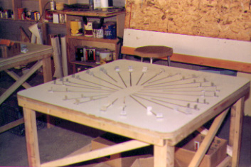
Duane Cutler sent along some photographs of a clever jig he has used to make his fuselage frames. He has used one jig to make all of the fuselage frames. The jig is a plywood-topped table which has been covered with white Formica. On this, he has laid out the curves of all of the fuselage frames. The laminations are held in position by 3/4" aluminum angle brackets. These are bolted to the table, and he has cut slots in the table top with a router so that the angle brackets are adjustable.
The jig can be used as a male or female form, and when using the jig, Duane forces Visqueen polyethylene film over the angle brackets to act as a glue barrier to the table top. The jig is also used to assemble the interior parts of each frame.
|
From "Construction Notes" Falco Builders Letter, December 1997 |
George Richards emailed, "I glued the forward tank mounting blocks onto frame 2 diagonal. Am I correct to assume that it is normal to have to remove quite a bit of that frame in order to make a flat face for the tank mounts to bolt on to? I have the frame 1 + 320mm station as being a little forward of the rear of the diagonal frame." George also sent along an emailed photo.
Something sounds quite amiss here. Normally, you don't have to remove any of the diagonal frame and the blocks that you glue onto frame 2 diagonal completely go around the frame. It sounds like the diagonal frame is in the wrong place.
|
From "Construction Notes" Falco Builders Letter, March 1993 |
Craig Bransfield sent along the following notes:
"I was having a little trouble locating the engine mount on the firewall, so I came up with the following procedure which may be of some interest to the builders.
"1. Place frame 1 face-up on a table and mark the forward face at B.L. 0 and W.L. 20 (thrust line location).
"2. Tie a pair of fishing lines across the Dynafocal ring to form an X with the intersection also at the thrust line.
"3. Hang a plumb bob from the fishing-line X with a loose loop, so as not to influence the point of intersection of the crossing lines.
"4. Hang an second plumb bob from the nose gear steering tiller bar pivot hole on the engine mount.
"5. Trial-clamp the engine mount to frame 1 starting with the locations for the brackets shown on the drawings.
"6. Level the entire assembly using only a spirit level set on the highest points on the Dynafocal ring. In my case, some compromise was needed here to produce the best average of measurements, and especially to be sure that I was not building in any 'up' or 'left' thrust.
"7. Note where the plumb bobs fall. The thrust-line plumbob should point to the mark on frame 1 and the lower plumb bob should fall somewhere on B.L. 0. If not, adjust the positions of the engine mount brackets, re-level the assembly, and try again.
"In my case, the upper left engine mount bracket came out spot on, but the upper right bracket ended up about 7-8mm 'low'. The nose gear retracted perfectly. No doubt these variations are due to warping of the mount from the heat of welding.
"I plan to jig up this assembly for fuselage construction by placing a piece of plywood in the Dynafocal ring to hold one end of the fuselage alignment string, with a 1/8" hole in frame 1 as a 'gunsight'. This way, I can be assured that the engine thrust line is neither displaced nor tilted from its design zero-zero setting."-Craig Bransfield
In this discussion, Craig does not mention the nose gear and its retraction mechanism. This is very important, and you need to put all the pieces together and make sure the nose gear sits in the middle of the nose gear bay and that the retraction mechanism works. Everybody who tried doing it without the nose gear and the retraction mechanism in place eventually had big problems.
|
From "Construction Notes" Falco Builders Letter, June 1993 |
Stephen Friend's windshield defrost system
|
From "Construction Notes" Falco Builders Letter, September 1993 |
Gary also says he's not sure where to install the washers when mounting the engine mount supports to the firewall. There are metal fittings on both sides, and asks where you put the washers-under the nut or bolt head. Washers are used to protect the underlying metal from the scraping action of turning a nut, thus washers are always installed under the nut unless otherwise specified.
|
From "Construction Notes" Falco Builders Letter, September 1993 |
By the way, when I first started to learn about aircraft fasteners, I was surprised to find that there were a number of specialized bolts and screws that were absolutely identical-most of them internal-wrenching bolts/screws. I became puzzled about the difference between a bolt and a screw, and it comes down to this: a bolt is a fastener that is prevented from turning while a nut is screwed onto it, while a screw is a fastener that is turned when it is installed. That's it, and you will find identical heads, shanks and threaded portions on both.
|
From Falco Builders Letter, March 1992 |
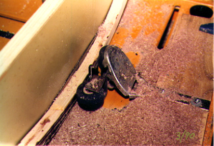
My Belly
by Steve Wilkinson
If anyone cares, I think the effects of a gear-up landing can be mitigated by the addition of a 20mm-square oak or hard maple strip, 420mm long, beginning 75mm aft of the rear end of the nosewheel bay and affixed longitudinally to the outside belly skin along the bottom longeron.
The hardwood strip has to be fitted to the slight curve of the belly, of course-it won't bend-and can be tapered somewhat as long as you leave the meat of the wood intact. I've made such a strip but haven't actually affixed it yet. I'm still wondering whether maybe it would overstress the bottom longeron if you did a belly landing and dropped it in. That would be a bigger pain in the ass than reskinning some of the belly.
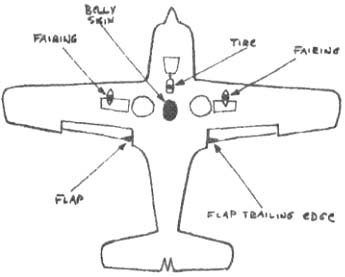
The diagram appended shows the points of contact of my airplane when Mark belly-landed it-the black areas-and I've tried to make them in scale and proportionate: the nosewheel tire, the belly itself, the tops of the flaps and a small portion of each fairing blister as shown.
It would seem that out of this experience we might develop a procedure for intentional emergency gear-up landings, now that we've had at least two (mine and Jonas's) mechanical problems with the gear itself.
Level the prop, certainly, though I wonder if you can slow the Falco enough to get that to happen. My thought is that extending the flaps fully means you're certainly going to have to repair them and possible splice-repair at least one cracked flap spar, as I did, but that the consequences of saving the flaps by leaving them up are worse. The extended flaps act as outriggers-they're remarkably strong-keeping the airplane erect and supporting it somewhat, saving more extensive damage to the belly and sparing the bottoms of the wings, gear doors, wing tips and-most importantly-those heavy aluminum plates fastened to the wing spar that act as a pivot point for the landing gear retraction mechanism. (In fact, one of mine was smoothly sanded down about a quarter of an inch. Any more and I'd have had to dig into the wing to replace it.)
Another question would be, do you land on the concrete or the grass alongside it? Certainly Mark's landing on the concrete at Bedford was as neat as could be, just like landing on a huge piece of extra-coarse sandpaper. It would be nice to think you could land on dewy-wet grass with a surface like a putting green, and perhaps get away with no damage at all-in such a situation, I'd even leave the flaps up and figure I'd get nothing but grass stains on the belly and wings-but one unexpected rock or stone hidden in the grass could do a lot of damage.
|
From "Construction Notes" Falco Builders Letter, June 1992 |
John Devoe wrote in asking about a drawing for the cabin air inlet. He has already purchased a plastic scoop from Aircraft Spruce. John then learned from Jonas Dovydenas that we had already designed a scoop. We have this as part of our 'advanced builder memo' series, future construction manual chapters-to-be that are not quite finished.
I looked at the plastic scoop some years ago and found it really didn't suit our needs. First, it was rather small, and the little threaded nut control on it was admirably simple, but it didn't seem to fit in well with a fuselage with two plywood skins. In the end, it just seemed simpler to make the whole thing out of wood. That's what everyone does now and if you follow the drawing, it will really blast some air into the cockpit.
Just in case you're thinking about what a smart guy I am for designing a system that works so nicely when others don't, let me set the record straight: it's mainly a matter of luck. I measured a vent on a Frati Picchio once in Milan, and it was about three-inches across so I decided to use that size even without asking anyone if it even worked well. Then the location on the side of the fuselage was primarily dictated by getting the vent down low enough so that the outlet would be below the instrument panel. Why our vent works wonderfully and a slightly smaller one in a slightly different location works not at all is a mystery to me.
|
From "Construction Notes" Falco Builders Letter, March 1991 |
Jim Petty asked about the installation of Fiberfrax insulation on the firewall and whether it should be installed under metal fittings. The answer is that you absolutely do not want to install the insulation under any structural metal component like the engine mount lugs or nose gear fittings, because it would contribute to loose bolts and could be very dangerous. It is less critical under such things as the bolt heads for the rudder pedal mounts and in situations like this and other minor screws and bolts you may do it either way, but most builders make a 2mm plywood pad for all fasteners and omit the insulation at those areas.
|
November 1998 |
Just wanted to let you know so that other builders will be
aware that if you install the left hand
throttle modification, you will have to do one of two things:
1. Adjust the height of the NACA
vent
-or-
2. Make a very close adjustment
mechanism for the air vent.
Bill Russell
|
From "Construction Notes" Falco Builders Letter, September 1991 |
Larry Black said that when he bolted the tail cone on his Falco, he wanted to seal up the crack so you wouldn't see it and still have the ability to take it apart. He used automotive drip-check seal for the joint. This is something used on the little 'gutter' on the top of a car. 3M makes one such product, and you can get it at an automotive store. Larry just ran a bead around the frame and bolted the tail cone on. The sealer squeezed out, and he wiped all the excess off with a paint solvent. The sealer is paintable and dries to a flexible substance.
|
From "Construction Notes" Falco Builders Letter, September 1991 |
Several of our builders have pointed out that the construction manual does not say when to put the blocks of wood in the bottom of the airplane that support the flap torque tube support and flap motor supports. Nor does it say when to install these metal fittings.
I haven't had time to study this one-and if anyone has a notion about when the best time would be, I'd appreciate knowing about it-but it appears from the way we build the wing, and then the fuselage that there is no good, ideal, now-is-just-right time to install the things.
It looks like one of those things that will always be difficult. But because of the difficulty in drilling the holes in the wood blocks, you might consider drilling the holes in the wood blocks first, and then fitting the blocks into the airplane, shimming and cutting as necessary. In reality, as long as you get them glued in to their neighboring longerons or frames, that's fine, because the important joint occurs when you glue on the skin.
|
From "Construction Notes" Falco Builders Letter, September 1991 |
Also, I'm told our construction manual does not say when to install the steel anchor plates that back up the engine mount lugs. What you normally do there is to fit them when the plywood skin is glue in place on the sides-i.e. from upper side longeron to lower side longeron-but before the upper or lower fuselage skins are installed. This way, you can clamp the parts in place, mark the places with a transfer pumch, take the pieces over to a drill press, drill the holes and then install them on the airplane. You can also start drilling the holes for the screws which go through the sidewalls by drilling the steel plates. Later after the fuselage is completely skinned, you can climb into the airplane and drill the holes through the wood.
|
From "Construction Notes" Falco Builders Letter, September 1991 |
And Howard Benham points out that the floor supports (see Figure 20 of Chapter 23) on the forward face of fuselage frame No. 3 should not be permanently installed until P/N 717 is installed. That's because you have to put P/N 717 in upside-down to drill the holes (see Figure 6 of Chapter 27).
|
From "Construction Notes" Falco Builders Letter, December 1991 |
I get questions about insulating the interior of fuselage frame 1 and the cockpit side walls. Some builders have filled the cavities of fuselage frame 1 with foam to cut down on cockpit noise. Others have done nothing. As far as I know, it doesn't hurt anything and may help slightly on the noise level. Some people do it and others don't-and I couldn't tell you if it makes any measurable difference.
And on the side walls, I think most builders have put some foam or fiberglass insulation in there, largely to insulate for heat and to cut down on wind noise. The production Falcos did not have any foam or insulation in the side walls and I've never noticed a problem. Again, it's okay if you want to do it, but I really don't know if it's necessary. It's one of those things like spanking tiny infants or microwaving cats-if it makes you feel better, do it.
|
From "Construction Notes" Falco Builders Letter, December 1991 |
I also get a lot of questions about the firewall, the Fiberfrax insulation and the plywood padding underneath. First, take a look at Section G-G on the cowling installation drawing (Drawing No. 134, Sheet A13e). We use a 25mm-wide strip of 2mm plywood around the outside of fuselage frame 1 for several reasons. The engine mounting requires some 2mm pads, and by running a strip around the outside, you create a level surface for the cowling supports and the firewall to sit on. The gap that remains is filled with insulation.
This is how Steve Wilkinson added plywood to his frame No. 1.
Now there are numerous places where bolts go through the frame-for the exhaust hangars and rudder pedals. What everyone does there is to make little 2mm plywood washers and glue them in place. This gives the bolt a solid foundation to clamp upon, the firewall doesn't get squeezed down Godforbid, and you just use insulation in the low areas.
This whole scheme gets a little messy down at the bottom. Steve Wilkinson, for one, just carried this scheme around all 'borders' of the frame.
|
From "Construction Notes" Falco Builders Letter, December 1991 |
Builders also ask about the opening for the rudder pedal cables, where they come through the firewall. I've thought about various schemes like a rubber bellows-shaped boot over it, but there's not enough room, and I doubt it's worth the trouble. This is one of those areas in the airplane where things aren't as neat and tidy as you might like, but it's also not worth a lot of mental effort.
Begin by drilling a hole through the firewall and the fuselage frame that's just big enough for the cable to get through. On the firewall side, make a little rubber or leather seal to pinch up on the cable to seal against the cable. I'd just cut two or three round patches of leather, say 30mm in diameter, punch a 1/8" hole in the center, and then make a single cut from the hole to the outside so you can slip the disks over the cable. By using several pieces of leather you can rotate them so the cuts don't align with each other. Then cover that whole mess with a little ring (or split ring) of aluminum-heck just make them out of hardware-store washers-and install them with a couple of sheet metal screws.
That way it will seal nicely against the cable and won't let any appreciable amount of engine-compartment air into the cockpit. On the aft side, you can put insulating foam right up to the cable and just let it rub.
Don't worry about friction, you have so much power in your feet, you'll never notice a slight drag from the seal.
|
From "Construction Notes" Falco Builders Letter, June 1990 |
Guess who wrote this:
When Steve Wilkinson discovered that the nylon bearing inserts for the rudder pedals are slightly oversize and won't fit onto the rudder-pedal support tubes, he bought a roll of industrial Teflon tape with which to make his own bearings. (This tape is entirely unlike Teflon "plumber's joint tape"; it's 10 mils thick and sticky-backed, designed for shop and factory use in situations where dry lubrication is needed.)
Unfortunately, the smallest quantity available was a 36-yard roll one inch wide: $80.00. Wilkinson estimates that he used about two feet's worth for the rudder-pedal bearings and will use another couple yards to line his ailerons and flaps where they bear against his sheet-aluminum trailing-edge hinge-gap fairings. Since that doesn't leave enough to entirely cover the wings in order to achieve greasy-slick laminar flow, and since the only other use he could think of was to build temporary air-show wingwalks so that the brain-dead spectators who feel free to clamber all over parked homebuilts would fall on their asses, he's offering the remaining 99 percent of the roll for the needy, homeless and bearingless.
Let him know if you'd like enough to build your own rudder-pedal bearings, and he refuses to charge anybody for that small a quantity. If you're intrigued by the airshow-wingwalk idea and want a considerably larger quantity, send $2.25 for each yard you want and whatever you estimate postage will be. He says snug rudder-pedal bearings can be made from a base thickness of a wrap or two of plastic electrician's tape on the rudder-pedal support tube and two perfectly cut thicknesses of Teflon tape atop it. He's Stephan Wilkinson, Box 455, Cornwall-on-Hudson, New York 12520, 914 534-7601, fax 914 534-5101.
Hmmm. That writing style has a familiar wring to it. Actually, the problem with the tight fit on the rudder pedal bearings is due to Dave Thurston's failure to account for the outside diameter tolerance of 4130 steel tubing-in that size it's normally three to five thousandths oversize. In the kits we are now shipping, the pedals are bored to a larger size, and you shouldn't have the problem.
|
From "Construction Notes" Falco Builders Letter, June 1990 |
Garry Wilburn sent some notes of how he is making the fuselage frames. He is using the method described by Jerry Ward in the December '85 Builders Letter, but with a few simplifications. Garry located W.L. 0 and the aircraft centerline at the middle of a sheet of 1/2" plywood, and then laid out all of the 15mm thick frames (except those at stations 2, 3 and diagonal 6) because these frames will all nest within each other.
Once the shapes were drawn on the 1/2" plywood, Gary clamped the 1/2" plywood to a sheet of 3/4" plywood and used one-inch drywall screws with the screws on 5" centers and about 3/8" out from the mold lines. The screws serve as alignment pins so that the 1/2" plywood can always be put back in exactly the same place-when I make a jig I use steel dowel pins for this purpose.
Garry then removed the screws, and bandsawed the shapes out of the 1/2" plywood so that each fuselage frame mold was a separate ring about two inches in width. Gary said that when he gets around to laminating the frames, he will remove alternate molds to make about four of the frames concurrently.
|
From "Construction Notes" Falco Builders Letter, September 1990 |
Garry Wilburn writes, "I have come up with a possibly innovative method of machining these [fuselage frame] components. After laminating, I screw a lamination down to the 3/4" jig board, screwing through the future longeron cutouts, and countersinking the head below the finished surface. After machining the first face, I simply turn the lamination over, and screw it down again using the same holes, now countersinking the other side.
"The actual machining, except for a final light sanding, is done with a router with a 1-1/4" carbide bit. The router subbase is fitted with a 12"-square, 3/8"-thick plexiglass base, which is fitted with 3 good-quality furniture casters, so that it can be maneuvered at an adjustable height above the jig board. I find that with a bit of experience, it's easy to machine within 5 thousandths of an inch!"
If you use Garry's method of machining the fuselage frame, be sure to use brass screws, because a carbide bit will explode if it hits a steel screw, particularly a case-hardened drywall screw.--Scoti
|
From "Construction Notes" Falco Builders Letter, December 1990 |
Marcel Morrien reports that he didn't use C-clamps to clamp the fuselage frame in the fuselage assembly jig. Instead, he made his own "integral" clamps by using a few blocks of wood and a screw-see sketch to the right. He was almost embarrassed to mention it because it was so simple, but then again there are a lot of us that didn't think of it.
|
November 1998 |
I have decided to relocate the NACA vents to approximatly 100mm below where I had them to facilitate the air vent from being interfered with by the left hand throttle mod. Do you know if there will be any problem in this?
Bill Russell
I don't know of any problem. When I located them, I was trying to put them as high as possible without interfering with anything.
Alfred
|
From "Construction Notes" Falco Builders Letter, September 1989 |
A question: on the belly of the airplane, wedge-shaped wooden "ramps" are glued laterally to the wing spar to carry the belly skin over the bottom-most side and center longerons. The two bottom-most side longerons are 20mm thick, and the center longeron is 15mm thick. The obvious choice is to sand the ramps, and the side longerons, down by 5mm-flush with the thickness of the center longeron-or build up the center longeron with a 5mm longitudinal ramp in that area so that everything is flush with the existing ramps and side longerons. Which way is preferred?
Steve Wilkinson
The 20x20 stringers should be sanded down to match the rest. The stringers are used as a gluing strip to form the wheel well door hinge "corner" between the bottom fuselage/wing skin and the side wall of the wheel well door. If no wheel well doors are going to be installed, the stringers serve to support the laminated ring for the "open air" installation. And in either installation, they serve a useful function in the event of an embarrassing slide on the runway.
Alfred
|
From "Construction Notes" Falco Builders Letter, December 1989 |
I haven't yet had the time to work out a list of plywood for the fuselage construction, but Howard Benham came up with this list: 9 sheets of 2mm 50"x50", 3 sheets of 2.5mm 50"x50", and 4 sheets of 1.0mm 50"x50" or 48"x48". Anybody want to comment on that?
|
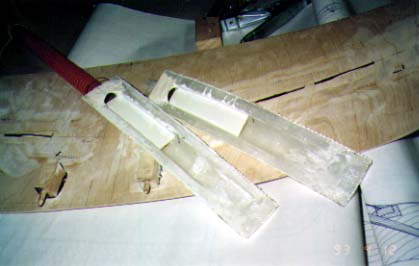
Here is Larry Black's jig for bending the plywood for the fuselage. |
|
To form the plwood, wet the plywood overnight, wet the canvas and clamp the top over the plywood on the bottom form. Allow the plywood to dry overnight before removing. |
|
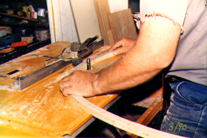
From "Construction Notes" Falco Builders Letter, March 1988 |
Steve Wilkinson and I have been trading notes on the method of skinning the fuselage side panels. These 2.5mm plywood skins have a slight compound bend that never ceases to frighten builders, but it is also remarkable that most builders don't remember much about putting the skins on. The production Falcos were built by wetting the plywood pieces and clamping them in place. After the plywood was dry, the now-curved plywood pieces were glued in place in the normal fashion.
The problem with this method was that the bend in the plywood was rarely smooth. You could see each fuselage frame very clearly. Larry Black developed a bending fixture that a number of builders have used with success. It is a lattice-work of wood and the plywood is held in place with a frame with canvas stapled over it. (We published a drawing of this years ago in a builder letter and can send you a copy if you are interested.)
A lot of builders have simply installed the skins dry. This seems to be the easiest and fastest method. Jim DeAngelo said that these skins were actually the easiest skins to install on the entire airplane. When they are installed dry, the plywood takes a beautiful, seamless bend. You apply the glue and then staple the devil out of it, working your way from the center out so that you don't create a large "bubble" to work out.
All of the builders who had installed the skins dry, however, did so before the wing was skinned. This made it easy to staple the plywood to the bottom side longeron. When you build the wing according to our construction manual, the wing is already skinned when you skin the fuselage. The one complication is that it is difficult to shoot staples into the bottom side longeron.
The safe approach is to prebend the skin with Larry Black's jig and then glue it in place. If you want to install the skin dry, the approach would be exactly the same as all of the other builders, except that you can't get that staple gun in there onto the bottom side longeron. You can, however, lay the staple gun on its side and shoot in a lot of "one legged" staples, where one leg is completely buried and the other is not. There's really nothing wrong with that at all, although it looks messy. Steve did it a slightly different way, but let me put him on the phone to explain it.
"Taking to heart your advice that wetting and prebending those panels in place leads to possible concavity of the inter-frame areas as the panels dry-and refusing to waste time making the fussy wood-and-canvas jig for preshaping the panels in a compound-curved male/female mold-I therefore am installing the panels dry and muscling them into place, as other builder successfully have. What I'm finding, however, is that it's easier to glue each panel in three steps-possible two-rather than trying to glue, clamp and staple everything all at once. When I do the latter, I find that by the time I reach the end of fastening one area, another has consequently begun to bulge and lift, or I end up with 95 percent of everything neatly glued and stapled, but I have a bulge or crimp that's simply too big to get rid of.
"So I first glue each panel to the bottom side longeron and let it dry, then glue the panel to the vertical frame(s) that runs up its center, then finally glue the remaining longeron/frame joints. (I'm using 50"x50" plywood sheets, so I can only span three or four frames per panel.)
"This way, the panel doesn't squirm and buckle uncontrollably enough to put me into my usual oh-God-the-glue's-setting-and-I-just-stapled-my-thumb condition. Steps one and two could doubtless be combined by anybody slightly more competent than I am.
"I also think that temporarily clamping the entire upper part of the panel wherever possible along the dry, unglued joints before gluing the bottom-side-longeron joint helps to establish a "set" to the plywood that begins to create the compound curve that the panel will ultimately accept. In other words, that first glued joint is actually slightly bowed under the resultant pressure rather than the straight joint it would be if you just glued the plywood to the longeron in the simple curve it would most easily accept.
"Finally, it's important to start at the bottom joint and work up; that way, glue and hardener can be applied from the top downward during steps two and three, running down into the decreasing-gap areas that would otherwise be inaccessible if you were stuffing glue in from below the fuselage."-Steve Wilkinson
Steve is using Aerolite, so if you are using a slower-setting glue you could do all of this at once. I do believe that not clamping the whole sheet into its final position when you glue to the bottom side longeron is an invitation to disaster. The only thing that I see about this technique that is questionable is the very slight possiblity that there would be small areas of unglued wood where the glue was not completely stuffed down to meet the previous joint. I think that would be more of a theoretical concern than a practical one. Lordy, if the Falco had that small a margin of safety, we'd better all go home.
|
From "Construction Notes" Falco Builders Letter, June 1988 |
Steve's Scupper
Having now temporarily mounted my rear fuel tank and snugged up the two restraining straps, it becomes obvious that the tank is not absolutely immovable. It doesn't move much-maybe an eighth of an inch or a little more-but I should think that under high G loadings, it's going to shift slightly. Therefore no overflow-catching "scupper" around the filler neck that is also mounted to the airframe-thus totally isolating filler-neck spillage from the inside of the tailcone-will work. It'll eventually crack or break loose, unless it's some kind of flexible arrangement such as a small sheet of neoprene or something attached to the filler neck, and around its periphery, to the filler-door framing.
So what I've done is cut down a small 59-cent hardware-store metal funnel and mounted it as a catchbasin around the filler neck, with a little piece of copper tubing brazed to it and a neoprene line leading from it overboard. When I mount the tank permanently, I'll epoxy the cut-down funnel to the base of the filler neck.
The funnel is the kind that has a max diameter of about 5". Stick it, intact, into the filler neck and draw a line around it where it butts against the I.D. of the neck. Hacksaw it off at that point and grind/file/sand it down a little farther for a snug fit around the O.D. of the filler neck. Braze or solder closed the funnel's seam, which is usually just a jam-fit narrow overlap, and solder a 3/4" length of 3/16" (or whatever) copper tubing as low down on the cutdown funnel as you can conveniently get it. Attach a neoprene line to that tubing and daylight it through the fuselage skin-either straight down and through the bilge, or out the fuselage side skin just above the side longeron if you want to run the shortest possible length tubing. Or hey, live dangerously and run it right into the battery box!
Incidently, your drawing showing the routing of the plastic lines from the fuselage-side static ports doesn't take into account the fact that the fuselage frame to which you're showing the lines Ty-Rapped is also the frame that supports the aft end of the battery box, thus making it impossible to Ty-Rap the line from the left static port in the manner shown on the drawing unless you drill holes through the battery box wall. It also necessitates reversing the orientation of the lateral lines, putting the shorter one on the right side of the airplane.
Steve Wilkinson
Production Falcos have an aluminum cup that is riveted with soft aluminum rivets to the fuselage skin. This crude, hand-hammered cup has a turned-up lip at the filler neck that fits loosely around the filler neck-with about a 2mm gap-and it is easily sealed with silicone rubber compound. The rubber is flexible enough to move with the tank, and I doubt that my well-seated tank moves as much as Steve's does-but maybe that's just the difference between rubber and felt cushioning. I can also tell you that if you have a scupper like mine, you don't need a drain line. When you spill fuel, you just flip the fuel out with your finger, and the thing will be dry before your gasperson has driven away.
The scupper that I keep thinking about is something like a wooden salad bowl. Cut a hole in the bottom to fit loosely around the filler neck, epoxy it to the skin, and seal around the filler neck with silicone rubber. And if you can't flip all the gas out with your finger, just con the airport cocaine addict into snorting the stuff.
Alfred Scott
|
From "Construction Notes" Falco Builders Letter, March 1987 Don Stark sent along the following notes on building the fuselage: |
I read about elaborate fuselage jigs that require skids of plywood and tons of bolts only to be in the way before everything is stabilized by the skin. The simple way is to let the fuselage jig itself. Four things are necessary: a good water level, plenty of dry line-chalk line without the chalk, four straight 4x4s, six feet tall with heavy bases that can be sand-bagged so they will not move, and a plumb bob.
The wings are built vertical as per the manual and the No. 6 frame carefully clamped or glued in place. Set the wings horizontal with the tips level in relation to each other and the No. 1 ribs at their exact angle of incidence. Now, set one 4x4 stand about two feet ahead of the center wing and another where the main fin spar can be attached to it. Measure from the main spar to establish where the main fin spar will be. Weight the bases and stretch a dry line between the two stands.
By measuring and "bumping" the 4x4 stands, the dry line becomes both the water line and butt line. Be sure to measure from each wing tip to the forward and back end of the dry line to be sure the whole structure is square. You now have the perfect reference to set the No. 4 and 5 frames. When 4, 5 and 6 are set, the side longerons are glued and clamped to them. Clamp 1x2 cross-members on the 4x4 stands to support the longerons. The rear stand will support the ends of the longerons through the complete process of setting the frames. The third and fourth stands with their 1x2 cross-members are "leap frog" back as each frame is set.
They are mobile so they can be slid from side to side and the cross raised or lowered to set the No. 7 frame exactly where it should be by measuring from the dry line. Use the plumb bob to set the frames exactly perpendicular. Set the No. 8 frame the same way and install the top and bottom longerons supported by the stands. Set each frame by the same process back toward the tail and the No. 3 and No. 2 frame forward.
The negative side of this method is the continual monitoring of the dry line to make sure the reference line is correct, but this is more than offset because you don't have to work around a lot of garbage or worry about knocking it out of line while removing a jig. The two mobile stands are used whenever necessary for support. I found that it was important to maintain and use the reference line until all the of the upper skin was installed, and the results came out perfect.
Don Stark
|
From "Construction Notes" Falco Builders Letter, June 1987 Steve Wilkinson's Black-Pipe Fuselage Jig. I am working on a chapter for the construction manual on building the fuselage. In it, I describe supporting the fuselage jig with two posts-one in the nose gear bay where it will be out of the way, and the other a "split" post of two boards on each side of the bottom center longeron at the tail section. Obviously, you will need to brace this well. But before I got him a copy of this chapter, Steve Wilkinson built a support with pipes, which considering the undulating nature of his barn floor was probably a good idea. So, if you have a ready supply of pipe and if your floor is like Steve's, you might want to consider his method. Here's Steve: |
My wing rests on two Sears Jackposts and a one-by-two leg clamped to the rear of bulkhead #6. The stand for the fuselage jig is made of standard black steel plumbing pipe, threaded where appropriate, and ordinary hardware-store fittings. It's a very robust affair, adjustable at each foot, and requires no skill and universally available materials to construct. Just like the Falco, in that sense. I had virtually all the pipe and fittings already, so that made it especially cheap. If you start with nothing, however, it won't be: pipe ain't cheap, threading costs extra and the fittings are each $2 to $5.
But it's as solid a stand as I can imagine, and is easily adjustable to any flooring variations, levelable in every direction. If you've seen my barn, you'll know why I needed that. It'll move if you grab it with two hands and heave, but you aren't going to just bump it out of position. The "bedstead" of mine is wide enough that I work inside it, but I suppose one could also make it narrow enough to stand outside the frame and work "through" it.
Steve Wilkinson
|
From "Construction Notes" Falco Builders Letter, September 1987 |
I have slowly come to realize, from staring at them, that corner blocks such as those fitted at the junctures of the longerons with frames 8 gain their strength not simply from the joining of block to longeron and to frame-the latter a relatively weak end-grain joint in any case-but from the fact that the corner block should be fitted in a way that allows it to be sanded smooth so it completely contacts the fuselage skin as well at the longeron and the frame. The skin thus provides the real strength, tying corner blocks, longeron and frame together as virtually one piece.
Until I figured this out, I'd been mounting some of the blocks so they were slightly inboard of where the skin will be and am having to now build the blocks up with a thickness or two of plywood so they will mate with the skin. I think this is worth a mention in the builder's manual-one of those things like bending plywood with the grain rather than against it: obvious to anybody who's done it before, but otherwise it becomes on-the-job training.
Steve Wilkinson
|
From "Construction Notes" Falco Builders Letter, September 1987 |
I get lots of questions about headroom in the Falco. What can you do to get more? If you are tall, my first advice is to stick with the standard canopy, and remember that the seat tracks are angled so that you get greater headroom as the seats are moved back. If the standard canopy and seat installation is not enough, there are some tricks you can pull.
First thing is to shave down the supports for the seat tracks. As things are designed, the seat clears the center console and cockpit side wall by about 10mm. You can get about 10mm more headroom by lowering the seats. Karl Hansen also shaved down the back of the seat track supports. This throws the seat back at a greater angle and some people have found this not to their liking.
Next thing is to make a bowl in the seat bottom. I don't advocate cutting the seat cushion down at all. Jim DeAngelo did this and found that taking an inch off was just enough to bring his tail bone in close proximity with the hard bottom of the seat. As it is designed, the seat cushion is very nearly the minimum you can have. The alternative is to create a little pocket for your bottom and let the cushion press down into this. You will be limited by the seat tracks, but you should be able to get about an inch of additional headroom.
If you just gotta have the Nustrini canopy and can't fit under it, there is still hope. Joel Shankle (six-five but short in the back) came up with a little wrinkle. He raised the canopy by 32mm-that's 1-1/2"-by install-ing a strip of spruce on top of the cockpit coaming. The windshield bow is installed on the "forward" side of frame No. 4. This allows him to still use the standard Nustrini canopy with only a minor amount of finagling. The dorsal fin has to be raised by 32mm as well.
The complications caused by this are relatively few. The windshield is no longer an exact fit, but that is not a major problem. The canopy skirt fairing must be extended, and that is one mean job. Pawel Kwiecinski has done the "high Nustrini" installation and says that the canopy installation was the hardest part of building the Falco-they celebrated its completion with a bottle of champagne. Because the canopy skirt is so long, it will interfere with the battery box door. This is not a difficult problem to overcome. You can just install the door with four screws or a hinge at the bottom. The whole installation looks quite nice, and it's doubtful that many would notice the difference in the plane.
|
From "Construction Notes" Falco Builders Letter, September 1987 |
Bjørn Eriksen is building a Falco in his tiny one-car garage in Bodø, Norway. I had not thought that this was possible and some of the details of this amazing Houdini stunt escape me, but the shop is an inch or two wider than the horizontal tail. Eriksen says that "the wing is literally the last thing built." Clearly, he is building the tail, then the fuselage and finally the wing. The wing is built by standing the fuselage center section on end and building the wing as we show in our construction manual. This is the same method that Richard Clements and Jim Slaton have used. What is not clear to me is whether Eriksen plans to install the engine, cowling and canopy prior to building the wing. Once he has built the wing there is no longer room to install the engine and cowling, so that will either have to be done prior to building the wing or at the airport. I haven't thought through all of the ramifications of this, but Eriksen clearly has this intriguing idea worked out.
|
From "Construction Notes" Falco Builders Letter, June 1986 |
As you will see, the new drawings for the fuselage frames show a number of mounting points for the Christen separator, breather tee, brake reservoir, etc. on frame No. 1, and master relay, starter relay, altitude encoder, etc. on frame No. 6. If you have already closed up the frame and don't have the blocking installed, the best method is to use 3/4" dowels and a hole-saw of the same size. Cut a hole on the aft face only and glue in a dowel so that it is flush with the plywood and glue a round patch over that. Then drill through the whole sheebang for your installation bolts.
|
From "Construction Notes" Falco Builders Letter, September 1986 |
Serendipity strikes again. Jerry also showed me how he drilled the holes for P/N 717-that's the nose gear screwjack support that goes in the aft end of the nose gear bay. Drilling the four 3/16"Ø holes through the right side of the nose gear bay can be a problem if you don't approach the task in the proper way. The trick is to clamp P/N 717-2 bracket -without P/N 717-3 retainer riveted in place-on the outside of the nose gear bay wall and upside-down. As luck would have it, the bottom of the part-now at the top-can be aligned with the cockpit floor to properly position the holes. You need a long 3/16" drill. I didn't take note of how long Jerry's drill was, but it appears that 14" or longer would be ideal. A 12" drill might work, but it looks like it would be awfully tight.
You should drill these holes before you install any of the flooring supports, or you will box yourself in. Drill the holes early, and remember: do not install the P/N 717-3 retainer until the holes are drilled!
|
From "Construction Notes" Falco Builders Letter, September 1986 |
There are three ways to form the compound bends of the plywood for the sides of the fuselage. The simplest method is to wet the plywood and clamp it to the frames. This is the method used on the original production Falcos and by most Falco builders. Everyone agrees it's easy, but some builders haven't had good results since the plywood doesn't always take a smooth bend.
The alternative has been to bend the plywood in a jig. Larry Black was the first to do this. We published a drawing of his bending jig some time ago, and I'll put it in the construction manual. Everyone says this method works well.
The third method is to install the skin dry. I don't really understand this, but Jerry Walker did it and said it was easy and worked very nicely. I mentioned this to Tony Bingelis, and he said that he had done the same thing. Jerry said he just worked the plywood into shape by using his pneumatic staple gun to staple the skin to the frames. When he got through the skin was in place and all buckles were gone. Strange. I don't know what else to tell you except that I've seen Jerry's Falco, and the side skins are beautiful.
|
From "Construction Notes" Falco Builders Letter, December 1986 |
In our last builder letter, I mentioned how Jerry Walker drilled the holes for the nose gear screwjack support. I had figured that it would take a 14" drill so that the drill chuck would clear the fuselage frame, but Jerry was off murdering geese in Canada so I couldn't check with him. Jerry later reported that he used a 12" drill but used a small-chuck Black & Decker electric angle drill which he borrowed from a friend. The drill is an expensive ($280.00?) industrial tool, so you don't want to spend that kind of money to drill four holes. If you don't have a drill that will clear, you can get a drill extension which will work. Jerry bought 12" drills in 1/8", 3/16" and 1/4" and he has used all of them.
|
From "Construction Notes" Falco Builders Letter, December 1986 |
Because of space constraints, both Jim Slaton and Richard Clements have built the fuselage before the wing. Jim Slaton had planned to build a shop for his Falco but there were a number of delays. Without the space to build his wing, he built the fuselage but left the bottom longeron loose from frame 6 forward so that he could get the main wing spar in place.
Jim skinned the tail cone and the fuselage sides up to frame 5 or 6. After separating the tail section, Jim set up the fuselage in the vertical position and built the wing as described in the construction manual. In essence, the fuselage becomes part of the wing jig, replacing the centerboard. Jim has had no real problems with this approach and asked me to pass the word on to any of you who might be considering this method.
There is certainly nothing wrong about this approach. Each method has its advantages, and I continue to think that the wing-first method has the advantage of getting the pieces of the airplane glued together in the most logical order. But this is not a huge advantage, so if space constraints force you to build the fuselage first, have at it!
|
From "Construction Notes" Falco Builders Letter, December 1986 |
A number of Falco builders have made the bottom of the wing fillet of plywood. This is the section of the fillet from fuselage frame No. 6 aft. I've always viewed this with suspicion since I know what curves the skin takes. The original production Falcos used plywood, but I wasn't sure if the bottom was the same cold-molded plywood that was used on the top of the wing.
Joel Shankle is one of those builders who has built this part of the wing fillet in plywood, and since he is only a 20 minute Falco flight from Richmond, I stop in to see him often. All I can tell you is that the plywood method works, and you just have to take it on faith that a piece of plywood will take the shape. With the fuselage upside down, Joel marked the outline of the fillet on the fuselage bottom. Then he installed a piece of wood between the trailing edge of the wing and the fuselage (when viewed from the bottom, it looks like the wing trailing edge strip extends straight in to the inboard edge of the wing fillet). This strip of wood takes a bend as it arches into the fuselage.
Joel then cut the skin to fit everything but did not cut the trailing edge of the wing fillet. Then with the wing fillet bottom skin clamped in place, he drew the curve of the trailing edge and cut it. The remarkable thing is that a flat sheet of plywood will actually take the shape. I can't explain to you why this works, or why the concave bottom of the flaps extends into the wing fillet and then transitions into what looks like a compound convex shape at the aft end. But it does! And it looks perfect and is easy to install. Count me as a born-again believer in the plywood bottom wing fillet cult.
Jan Waldahl mentioned that he had used the same method and used foam and fiberglass for the upper wing fairing. "It was easy!" he said, and I can tell you that there is nothing about the appearance of his fillet that you can fault.
|
From "Construction Notes" Falco Builders Letter, December 1986 |
Mr. Hall was also confused by the spacing of the forward wing spar with the main wing spar. In redrawing the wing, I eliminated the wing draft, which showed that the primary thing that you are after is a dimension of 340mm from the aft face of the main wing spar to the forward face of the front wing spar. A slightly fat main wing spar made Mr. Hall think that his landing gear was the wrong length, the fuselage frames out of kilter... or something.
|
From "Construction Notes" Falco Builders Letter, December 1986 |
Builders making their own fuselage frames have used a variety of methods to get the frames to an even thickness. The best method is to use a thickness sander, but they are quite expensive, so the best you can hope for is to rent time on one-as Francis Dahlman does. A thickness sander attachment is now available for radial arm saws (see "Tool Talk").
Ben Burgoyne has used a jointer to rapidly finish his fuselage frames, supporting the frame with a homemade adjustable-height "dumb robot" roller. With this arrangement, he leveled the roller with the jointer and worked the frames around until the reached the proper thickness.
Bob Cordray used a Sears rotary plane mounted, as I recall, in either a drill press or on a radial arm saw. By simply passing the frame around under the device, the whole frame was planed to the exact thickness.
|
From "Construction Notes" Falco Builders Letter, December 1986 |
Because of the close proximity of the fuselage access door to the right stabilizer, it is best to install the access panel very early in the game. Once you have installed the inboard stabilizer rib on the fuselage you have seriously compromised your clearance for a router. Even then, an ordinary router may be too big, and you may have to use a router attachment on a Dremel Moto-tool.
|
From "Construction Notes" Falco Builders Letter, December 1985 |
Let's see if you can follow this. Jerry Ward made his fuselage frames and sent in a description of the method he used. What follows is a description of his method, which uses plywood for a female laminating form. One 4'x4' piece of 1/2" plywood is used for fuselage Stations 12, 11, 10, 9, 7, 6 and 5, made in that order. These laminations are 15mm thick, and Jerry made them 17mm to start with. The 1/2" plywood form insures that the lamination is higher than the form, making the sanding to thickness easy. The forms for all 20mm thick laminations were made from 3/4" plywood.
At the time Jerry made these frames, the formula for the fuselage frames was not yet available so he had to lay them out the old way of drawing all the diagonal lines. Because of the mess that would be created by doing this for all of the frames on a single piece of plywood, Jerry made separate half-patterns for each fuselage station. He used 1/4" Luan mahogany plywood, which he painted with white flat house paint. He laid out half of each fuselage station and cut these out of the plywood. He then used these to draw the shape of the laminations on the plywood form. Please note that with a programmable calculator and the fuselage curve formula, it should be possible to eliminate this half-pattern step.
On a 4'x4' piece of 1/2" plywood, Jerry drew W.L. 0 and the aircraft C/L, then drew the outline for Station 12. With a jigsaw, he cut to within about 1/16" of the frame outline. Remember, this is a female mold, so you should cut out the inside of the form.
Jerry mounted his 1/4" electric drill with sanding drum in a wooden frame to sand the inside of the form. Jerry's method effectively mounts the drill so that it is used like an ordinary router, and he would slide it around on the plywood. Because the plywood sheet is so large, you cannot use a sanding drum mounted in a drill press, but you could use a sanding drum mounted in a work table-like a large router turned upside down. Using the sanding drum, Jerry sanded the inside of the form at four places to the final inside dimensions. He did that at the top and bottom center and at W.L. 0 on each side. The form is to be mounted on a flat jigboard-also made of plywood-and this sanding will allow you to check the proper positioning of the form on the jigboard. (I am not convinced of the necessity of the work in this paragraph.)
Jerry drilled a series of small nail holes 3/8" out from the shape of the lamination. These holes are drilled every 2-1/2" or so, all the way around the form. The size of the nail holes were determined by the size of the nails that he selected to hold the form to the jigboard. The form was then placed on the jigboard, and Jerry inserted a nail into each hole and drove it to a depth of about 1/8". He then pulled all nails out and saved them for later use.
Jerry then used a jigsaw to cut the form 3/4" out from the shape of the lamination. Thus, he had a ring 3/4" thick that would fit the outside of the fuselage lamination. Jerry then attached his sander beneath the table and completed the sanding of the inside of the form, although it could also be done with a sanding drum mounted in a drill press.
Jerry covered the jigboard with a sheet of 4-mil polyethylene plastic and taped this in place. He applied a thin coat of paste wax to the plastic. (Jerry also reported that he found adhesive-backed plastic shelf paper good for covering up jigs-but in this case he wanted to be able to see through the plastic.) The inside of the form was lined with vinyl electrical tape.
Jerry placed the form on the jigboard and inserted the nails back in their old holes in the form and in the jigboard. At a width of only 3/4", the form is a little flimsy, and that is the reason for starting the nails earlier. The female form was complete.
Jerry used 17mm wide stock for the 15mm thick laminations-and 22mm wide stock for 20mm thick laminations-to allow for trimming to final thickness. Jerry installed the first four laminations with butt joints at the longeron cutout areas and then scarfed the rest on a stationary disc sander. He made a simple jig which allowed each scarf to be done in about 2 seconds. This consisted of a block of wood clamped right up next to the sanding disc. The wood block had a 1:15 slope on it, forcing the laminating strip to the proper angle. After the laminations were installed, clamps were applied and the glue allowed to set.
The initial bit of wood and glue squeeze-out was removed with a router mounted on a 1/4" aluminum plate. To raise the plate above the jigboard, Jerry used 4 C-clamps clamped to the plate. The bottom heel of the clamps was enough to do the job. With this arrangement, he trimmed the lamination to about 16.5mm thick.
The lamination was then sanded to 16mm thick. To sand the lamination, Jerry used a "sanding skid", nothing more than a sanding board or Disston Abrader mounted to 16mm thick pieces of wood, which raised the sanding board off the table the required amount. Jerry's sanding skid looks like an extra-wide snow sleigh, with sandpaper wrapped on the bottom side of the "seat". The skids were attached with countersunk nails up from the bottom, through the sandpaper and into the "seat".
Jerry then drilled four nail holes in each spruce lamination-one hole in each longeron cutout location-and he drove an 18 gauge 1" nail through each hole into the jigboard. These were alignment pins, and they were so Jerry could put his frame into the form later and have it in exactly the same position.
Jerry then removed the lamination from the form, turned it over and secured it to a flat table. He removed the glue (and about .5mm of wood) with a router to bring the lamination to 15.5mm thick. Using his sanding skid with 15mm thick "tracks", he sanded it to the final thickness. Jerry said he had trouble securing the lamination and finally made a vacuum table and let the suction from an industrial shop-vac hold the lamination in place.
The vacuum table was made with 2x4's and with a hole for the shop vac on one edge piece. There were holes in the internal cross bracing to let the vacuum pull from all quadrants. The table was covered with 1/2" particle board on each side and sealed with a bead of caulking compound before nailing the top and bottom down.
To use the vacuum table, Jerry would put the lamination in plance with a few small jig blocks to hold it in position. After tracing its outline, he removed it and drilled 1/2"Ø holes, replaced the lamination and turned on the vacuum. After the frame was sanded, he used a plug cutter to make 1/2" plugs and glued them in the holes. (Jerry advises that the noise of the router and shop vac is incredible and that you should use ear plugs.)
After sanding, Jerry put the lamination back in the form and added the internal bracing.
Jerry says "Repeat process about 16 times and begin assembly. Nothing to it!" He also offers a word of caution. "These female forms are flimsy, and after removal from jigboard, they should not be re-used unless nails can be driven back into the same holes, particularly on frame No. 12, so be sure to laminate all gluing strips before removing form from the jigboard."
This description may be just the thing you need to get started making fuselage frames, or it might be just what you needed to send off your check for the Trimcraft kits! In fairness to all, in the same time that Jerry has been making these fuselage frames, wing and tail ribs, and a few other parts including a canoe, Karl Hansen built his entire Falco. Jerry admits to a high piddle factor and holds the record on the wing ribs at 700 hours-but he enjoys working in his shop so the time is not important. Jerry's sandings skids are very clever, and there are other things that he has done here that are bound to be a help to anyone building a Falco.
|
From Bill Russell, November 1998 |
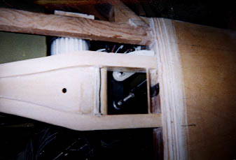
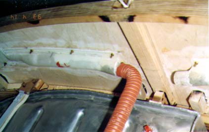
Before modification. Bill found the left hand throttle modification
interfered with the cabin air inlet.
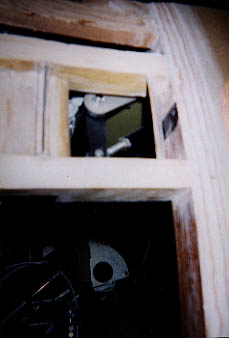
Another look at 'before'
Enclosed are pictures of the NACA vent and the interference from the left hand throttle modification. I have send you a picture of the before and after. The one nice feature of having to move the vent is that it will not interfere with the striping on the aircraft.
Bill Russell
After modification, the vent is lowered substantially.
Q: The Construction Manual states "use the master template" when describing the longeron cutouts in the fuselage frames. Are you talking about a full-size contoured template for each frame with the cutouts located per the dimensions in the drawings? Or, are you talking about a local template to ensure that the cutout is the proper dimension and tangent to the outside contour of the unfinished frame? What are the important criteria when locating the longerons and stringers?
A: By 'master template' I am talking about using a single piece of plywood or cardboard on which you have drawn the aircraft centerline, waterline zero and the waterline for the lower longeron. By doing it this way, you are working from a common template.
This keeps you from making mistakes if you tried to measure and locate the longerons for each frame separately.
|
From "Construction Notes" Falco Builders Letter, June/September 2000 |
Garry Wilburn sent us a sketch of a minor dimensional change that he made to P/N 805 to avoid mechanical interference with the flap actuator housing. I haven't heard that others have had any difficulty with this, but the change is a small one.
|
February 2001 |
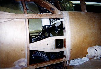
I'm confused about the supports for the inverted header tank. Drawing 121 tells me to make two supports. I've done that. The fuselage frame instructions tell me how to mount one on frame #7. I've done that. But I find nothing that tells me where or how to mount the second one. Do you have any more info you can provide me?
Doug Henson
The concept was to skin the fuselage and then mount the other support inside the fuselage. An alternative is to make a fuselage frame lamination for that location and put it in first. Take a look at what David Carroll did -- it's in the Falco Workshop.
|
From "Construction Notes" Falco Builders Letter, June 2001 |
Is it okay to scarf several pieces of 1.5mm plywood together to sheet frame 8? And on P/N 754 and 774 fin hinges, I have fabricated the angle portion from 25mm (or 1") material. Do you have to trim the short side to 20mm. I realize there is a weight penality, but I'm more worrine about a movement conflict. Also the radius the stock comes with looks nice.
Tom Webber
Of course, it's okay to scarf several pieces of plywood together for frame 8 or any other place in the airplane. I don't see any problem with a 25mm base width to the fin hinges.
|
From "Construction Notes" Falco Builders Letter, June 2001 |
I propose to put two coats of varnish over the forward surface of fuselage frame No. 1 before applying the Fiberfrax glue and the Fiberfrax. Is this proper, do you think?
Also, the construction manual says Wicks sells a non-flammatory paint which can be used to paint the walls of the nose wheel tunnel. Can you tell me more? I can't seem to find it in their catalog.
Garry Wilburn
Two coats of varnish before Fiberfrax is fine, and that's the normal way to do it. I'm not up to date on the paint. It was something they sold for a while that would blister up into a foam if it was hit by a flame.
|
From "Construction Notes" Falco Builders Letter, December 2001 |
From Doug Henson. "There are two 20x20 stringers on the bottom of the fuselage between frames 4 and 6. The instructions say that they are glued to the wing spar at the forward end. Should I make a 20x20 groove in the bottom of the wing spar for these?"
NO!
"Or are they glued to the bottom surface, then shaped to the outer fuselage contour? If the latter, there would only be about five millimeters remaining after contouring. I can't find this detail anywhere in the drawings."
That's right. If you wish, you may cut the stringers to fit against the main wing spar, so that they have a larger cross-section aft of the wing spar.
|
From "Construction Notes" Falco Builders Letter, December 2001 |
From the Netherlands, Niels Kinneging asks, "I am presently building the fuselage frames. Do I need to oversize them so I can sand them in the jig, or should I stick to the exact outside measurements as they are in the drawing? If all the frames are drawn with a forward view, then the fuselage frames number 1, 2, 3 and maybe 4 might, after sanding them for the plywood covering, be too small on the forward face. Is this a problem, or can I disregard this?"
Make the fuselage frames exactly to the sizes shown, but you may want to make the forward frame No. 8 slightly oversize. That's how we do it.
|
|
![]()