Angle-of-Attack Indicators
![]()
Angle-of-Attack Indicators |
|
by Cecil Rives
|
This article appeared in the September 2004 Falco Builders Letter |
In 45 percent of all fatalities in experimental aircraft the final killing event is uncontrolled flight into the ground due to stalls and spins. That’s according to James Frantz, inventor of Proprietary Software Systems’ Angle-of-Attack indicator. AOPA’s Air Safety Foundation states that “stall/spin accidents tend to be more deadly than other types of GA accidents, accounting for 10 percent of all accidents, but 13.7 percent of fatal accidents. Overall, around 20 percent of all GA accidents result in fatalities, but stall/spin accidents have a fatality rate of about 28 percent.”
The higher rate of fatalities in experimental aircraft can probably be explained by stale piloting skills, poor design or construction, lack of a stall warning device and low time pilots performing first flights on their pride and joy. (See Alfred Scott’s article “How To Kill Yourself In A Homebuilt Aircraft”) The ASF study also found that stalls/spins are most likely to occur in maneuvering flight such as: aerobatics, low passes, buzzing, pull-ups, aerial applications, steep turns to reverse directions or engine failures after take-off with pilot trying to return to runway.
One might also add steep turns to final approach when trying to correct an overshoot from base to final. As you know, most airports have a traffic pattern altitude of 1000 feet above ground level and some even lower than that. A NASA study in the late 1970’s found that a Piper Arrow requires about 1200 feet of altitude to fully recover from a spin. Obviously, recovery from a spin on final approach in most high performance GA aircraft would be unlikely.
A number of articles have been written recently on the effects of angle-of-attack (AOA) and extolling the virtues of AOA instruments. I have listed some of these at the end of this report as most of my comments are based on the information contained in those articles. In them you will also find a more in-depth study of AOA, particularly the two by Ed Kolano.
I know most of you are familiar with angle-of-attack, but it may be helpful to review what it is and what it does.
The AOA of any wing is the angle between the chord of the airfoil and the relative wind. Relative wind is the direction of flight. Lift is determined by the shape of the airfoil, wing area and AOA. As the AOA increases so does lift, provided the airflow over the wing does not separate from the wing’s surface. When the airflow separates due to excessive AOA, lift decreases and a stall occurs. This is called the critical AOA and is about 14 degrees in most general aviation aircraft.
Now, it is exceedingly important to remember that a wing will stall at any airspeed, at any altitude, at any power setting, and it always stalls at the same AOA. Fuel weight, ‘G’ loading or angle of bank have no effect on AOA. Airplane weight and accelerated maneuvering affect stall speed but not stall AOA.
Ed Kolano’s article (AOA) in the April, 2001, issue of Sport Aviation gives a comparison of an aircraft weighing 1000 pounds which results in a stall speed of 41 knots. The same aircraft when loaded to 1400 pounds has a stall speed of 49 knots. The stall AOA, however, remains the same.
There is one instance where the AOA of a wing will change and that is with the application of the flaps. Lowering of flaps changes the configuration of the airfoil and produces a corresponding change in the chord line.
If your first flight instructor was like mine you probably still have scars on your head from his pounding away with “Watch your airspeed! Watch your airspeed!” And, that was good advice as it was probably the only instrument you had that gave you any information as to the lift of the wing. Unfortunately the ASI is not very reliable and gives very little information about the lift conditions of the wing. Also, as speed decreases the error of the pitot-static system increases. In addition, it has considerable lag at any speed.
So, what is reliable? If the critical AOA is constant in nearly all conditions of flight and if AOA can be measured to provide a value of lift then an AOA indicator should be one of the most valuable instruments in your airplane. And that is precisely what an AOA indicator can do!
The Wright brothers had only one instrument on their first airplane—a stick protruding from the nose of their craft with a piece of yarn attached to it. So, the use of an AOA indicator has been with us since manned flight began. It is amazing that one hundred years later it is not a common instrument on GA aircraft. (The FAA does require stall warning devices on certificated aircraft). Most airliners have indicators installed but sometimes only connected to the autopilot. The information is not readily available to the pilot. According to Frantz, in 1957 the U.S. Navy and Marines cut their fatality rate in half in one year after they perfected and flew AOA in carrier landings. He says they ignore airspeed completely.
What can an AOA indicator do for a pilot? Well, for one, it can assess lift under any flight condition, at any speed or altitude and at any wing loading. The instrument is very sensitive at any airspeed and changes in AOA are immediately apparent.
Kolano states that there is an AOA that gives maximum range regardless of weight and a stall number that is correct whether you are straight and level or in a tight turn. He goes on to say that there is a specific AOA unique to every airplane that ensures the optimum speed and maximum range for every airplane weight and that your airplane will cruise farthest when you fly at its maximum L/D. (The maximum L/D, maximum endurance, Vx and Vy are all functions of AOA).
Frantz agrees that Vx and Vy do not occur at fixed IAS, but they do occur at the same AOA, respectively. He says that using the same pitch attitude for low and high density take-offs may put you in the “region of reverse command” and that by flying the proper AOA on rotation will insure a proper attitude regardless of density altitude or gross weight. Also, he feels that all approaches should be flown using a fixed AOA regardless of gross weight, bank angle, turbulence or density altitude.
About two years ago I purchased a Sport Model AOA indicator from Proprietary Software Systems for $895. (This is by no means the only indicator available. There is the “Bacon Saver” by O’Neill Airplane Company; then Safe Flight Instrument’s; Controlled Flight Mechanisms has one called “Huntington Lift Reserve Indicator; HCI AOA Indicator; Rite Angle 111b AOA and there are probably others). I picked Frantz’s because I had seen it displayed at Oshkosh and liked the idea of no vanes or other protrusions sticking out from the wings or fuselage and there are no moving parts. The system is fairly simple. There are two ports (.040-inch holes) one on the top of the wing and one on the bottom. (At Station #11 on the Falco’s wing; just outboard from the bellcrank inspection panel.) These are connected to 1/8” tubing that connects to the C.P.U. Pressures from the aircraft’s pitot-static system are also fed into the C.P.U. and the result is a calculation that gives you the coefficient of pressure at the ports in the wing. There is a unique variation of the coefficient of pressure with AOA.
The installation during construction of the Falco would be very easy and for the most part that is true when retrofitting it in a completed Falco. Except for one thing. That is the routing of the 1/8” tubing out to Station 11. There is a 1/2” plastic conduit through which the wing tip strobe and navigation lights cables are routed. I used that for the tubing and found it very difficult to pull it through. There is quite a bit of friction between the tubing, cables and the conduit. No amount of soap, silicone grease or talcum powder seemed to work. I finally pulled as hard as I dared and then held the pulling line static until the tubing “caught up”.
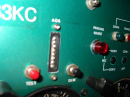
Perhaps someone might have a better method of installing the tubing. The C.P.U. is mounted on the aft side of Frame #6. The display is mounted as near the ASI as possible. (For a more detailed description of the installation, calibration and operation of the unit you may go to P.P.S.’s website: www.angle-of-attack.com).
After installation the unit is calibrated in the air during a short flight. There are two modes in which the AOA is measured: Flaps up and flaps down (15 degrees or more). Both are set at 1.15 x stall speed. At those speeds, the audio warning “Angle! Angle! Push!” will sound.
I have flown with it now for about 100 hours and feel that I have greater “peace of mind” than I did before. I suppose you could call it a security blanket. I make my final approaches a little slower (65 knots over the fence), and I think make better landings. AOA is controlled by the elevator and rate of descent with the throttle. (I still keep one eye on the ASI, though). There have been a couple of instances when the aural warning of “Angle! Angle! Push!” has been heard on my headset. Nice to know someone is monitoring the AOA.
References:
AOPA-Air Safety Foundation: Stall/Spin-Entry Point for Crash and Burn?
Frantz, James: Proprietary Software Systems Website, www.angle-of-attack.com
Goyer, Norm: AOA Indicators, Custom Planes, 12/99
Kolano, Ed: AOA, Sport Aviation, 4/01
Kolano, Ed; Goin’ the Distance, Sport Aviation, 5/01
Langewiesche, Wolfgang: Stick and Rudder
Lindstrom, Rick: Proprietary Software Systems, Kitplanes, 2/02
|
|
![]()