Notes & Comments
Landing Gear
![]()
Notes & Comments
|
|
|
From "Construction Notes" Falco Builders Letter, September 2003 |
From Christchurch, New Zealand, Bruce Frazier and Russell Woods report that they are now making steady progress after their 15 year layoff. Wing skins are all bent up for gluing when the warmer weather comes, and most of the metalwork is now done. They ask:
"The main gear oleo orifice fitting, No. 551, shows two holes 1.5mm. Is this correct? As the rebound damper No. 552 also have two 1.5mm holes, I would have expected No. 551 to have more holes or larger holes!"
Yes, the drawing is correct. The holes are the same in both parts for downward flow on the rebound, but the damper lifts up and allows for greater flow when the strut is being collapsed. In all cases, the drawings always mean what they say, unless we have issued a revision.
|
Aug 1998 |
Cleveland has an upgrade kit available for the Cleveland wheel (40-78B) and brake (30-9) assy specified for the Falco.
The part number is 199-93 and includes new linings, discs, shims, bolts, rivets, and nameplate. The linings are the same as the old (66-106) and the disc is the same diameter as before. However, the thickness increases from .495 to .608. According to the Cleveland tech people, the braking improvement comes from better heat dissipation from the new disc.
The formula they use to determine braking potential and requirements is as follows:
.0443 X Gross weight X stall speed in knots X stall speed in knots / number of wheels
According to Cleveland, the old brakes have a maximum potential of 117,500 ft/lbs of energy. The brakes with the upgrade kit have a maximum potential of 155,500 ft/lbs of energy.
Using their formula with the following values, I come up with a requirement of 116,972 ft/lbs of energy as the Falco requirement.
Gross weight - 1880
Stall speed - 53 kts
Number of wheels/brakes - 2
According to this formula, the Falco's requirement is pretty close to the maximum potential of the old brakes. The new kit should provide a comfortable margin. I have ordered this kit and will let you know if there is a noticeable improvement.
Jim Quinn
Jim_Quinn@amrcorp.com
I have the Cleveland brake upgrade installed and the brakes are much improved. Some additional info and corrections from my first email:
The thickness of the original disk as removed from the plane was .15, the thickness of the new disk is .30. The clearance between the disk and the trailing link arm is tight, but it does clear.
The weight of the old disk = 1 1/2 lbs or .6 kg, the weight of the new disk = 2 lbs. or .8 kg, so I picked up an additional pound of weight.
The best news is the braking action is much improved. I have the sensation of being able to stop when I want to rather than when the plane decides it wants to stop. I think this is a worthwhile change.
Jim Quinn
Jim_Quinn@amrcorp.com
|
From "Construction Notes" Falco Builders Letter, March 1996 |
Steve Wilkinson recently changed the O-rings on his main gear shock absorbers, and reports, "When disassembled, the oleo had a very small quantity of bushing bronze at the bottom of the strut fluid reservoir-probably enough to cover the head of an old-fashioned thumbtack. The main internal bushing showed the expected polishing of the strut having smoothed it in obedience to its track of movement.
"One thing that particularly interested me: a variety of people have predicted dire things because I use ordinary shop air and a strut pump to pump up my shocks, rather than nitrogen. 'You'll get all sorts of rust,' they've said, parroting the conventional aviation wisdom about why one should pay $50 a shot for nitrogen rather than using air. Well, there's not a spot of rust anywhere inside the shocks. The pieces are either aluminum, or where steel, so constantly saturated in hydraulic fluid that it doesn't matter what you pump in there. Anybody who is inflating their Falco struts with nitrogen because they think they have to is wasting their money."
|
From "Construction Notes" Falco Builders Letter, March 1996 |
Bill Roerig asks, "I recall having read in an earlier builders letter that the wheel well doors were not stiff enough. What seems to be the best remedy short of going with high-dollar graphite?"
I'm not sure there is an answer to this. In all cases that I know of, the wheel well doors appear to pull open in flight by about 1/2" to 3/4" at the outboard trailing edge. Originally, I thought this was a problem of stiffness with the doors themselves. Pawel Kwiecinski made his doors of Kevlar, and they still pull open. I have made a mold with very high reinforcing ribs, and we've installed a few of these on Falcos.
These doors are so stiff it's difficult to imagine that they could flex at all, yet I've flown behind a Falco with these doors (Steve Wilkinson has them on his Falco), and they pull open just like all of the others. The bottom line is that I really don't know if the problem is a matter of flexing in the door, the actuating linkage or both.
|
From "Construction Notes" Falco Builders Letter, September 1996 |
We have offered two types of main landing gears for the Falco. The Cleveland wheels use a standard 5.00x5 tire, while the Rosenhan uses a 5.30x6 boat trailer tire. We used the Rosenhan wheel because at the time that we began offering the Falco, Fred Rosenhan was a colorful homebuilder-machinist who delighted in making wheels for homebuilders and undercutting the prices of everyone else. And also, the 5.30x6 tire was one-half inch narrower when installed.
That half-inch has proved, over time, to be not worth the effort, and doors can be made which cover both wheel types. Fred Rosenhan has long since sold his business to a businessman who quickly realized that good ol' Fred was giving them away at cost all along, so the price advantage is long gone. And over the years, we've heard rumors and then reports that Goodyear would no longer make the 5.30x6 tire. As a result, we've phased out the 5.30x6 wheels and brakes and in the future will only offer the Cleveland variety.
But the availability of tires is still a concern, and thus we were interested to hear the following from Steve Wilkinson: "I've always been embarrassed by the chunky, industrial, coarse-treaded look of the Goodyear 5.30x6 four-ply tires that fit my Rosenhan wheels. They're so squared-off that I've been forced to explain to people that because I operate out of Upstate New York, I need snow tires. (You'd be surprised how many people-even pilots-accept that explanation as a logical one.) So when I recently decided to change my main-gear tires at 330 hours because the tread was worn in the center, though by no means bald, I went to the local industrial-tires supplier and ordered a set of Carlisle 5.30/4.5 x 6 six-ply forklift tires."
"They're more rounded than the squared-off Goodyears, particularly when you slightly shave the outside edges of the tread with a razor blade (which I'd also done to the Goodyears, to little avail). And the tread itself isn't patterned like a mountain-bike mud tire. The Carlisles fit the wheelwells just fine, even though my wheelwell-door-to-tire clearance was always minimal during the retraction/extension cycles with the Goodyears."
"As I remember, the Carlisles are rated for a load of 1,200 pounds (each, I'm assuming...), plus a speed rating that seemed rather minimal, but I'm sure it's conservatively based on a 12-hour-a-day near-constant industrial cycle rather than a 10-second dash to 70 mph a couple of times a day. I wouldn't want to step-taxi to the most distance runway at JFK at 50 knots on a hot day on top of them, but I'm sure for normal Falco use, heat buildup won't ever be a problem. Price was something like $35.00 apiece."
"One more tire note: A while ago, I had a left main shock strut that would bleed down to a point where it needed to be pumped back up every two or three months. It has since been fixed and holds air apparently permanently, thanks to the over-size oleo O-ring that Sequoia will supply on request for builders suffering this same problem. However, I once operated the airplane for a couple of flights with the strut to low, and as a result had to replace the nosegear tire prematurely. You'll be surprised how quickly the nosewheel tire will 'cup' and obviously wear asymmetrically-and thoroughly-if you try to operate with seriously unequal main-gear shock extension. Beware."
|
From "Construction Notes" Falco Builders Letter, June 1997 |
Bill Roerig asks, "I'm wondering what the specifications are for the main gear wheel alignment. There is very little that can be done about it anyway, but I'm curious as to 'toe in/out'. Camber? I've got 1mm toe-in at 14" diameter."
The Falco main gear wheels are supposed to be directly in line with the centerline of the airplane, and there's never been any specification on the limits for toe-in or toe-out. There's also precious little you can do about it, and I doubt there's much to worry about here in any event since airplanes are rarely built perfectly to the plans and the worst that would likely happen would be a little tire wear.
|
From "Construction Notes" Falco Builders Letter, June 1997 |
Bill also asks about the design of the screwjacks for the main gear. He says, "I take it from the drawings that P/N 603 screwjack end will be compressed into P/N 512 screwjack to give a positive lock on the side load struts. But, why then the springs arrangement?"
The Falco's landing gear is a mechanical screwjack design, with the desired intent that the three screwjacks will all arrive at the gear-down position at the same time. However, real life is seldom so perfect, so the design has springs to allow for imperfections in construction and for expansion and contraction of the airframe and components over time. The intention of the design is that the side load struts and the nose gear drag struts will go down and go 'over center' thus providing a mechanical lock. The screwjacks have springs in them to provide about 40 lbs of pressure on the struts to hold them in this over-center, locked position.
|
From "Construction Notes" Falco Builders Letter, June 1997 |
And from deep in Australia, Ian Ferguson faxes, "When rigging the undercarriage doors, I have found it difficult to satisfy all three parameters, i.e. doors closed, both gear up and down and also main gear doors missing the wheels. In the inverted position, the screwjack springs compress under gravity. If they are kept from compressing, then the doors easily miss the wheels giving more latitude for other adjustments. While one is not likely to be retracting the wheels in the inverted attitude, one feels that positive separation would be desirable in view of the chance that aerodynamic effects might compress the springs in some circumstances. One could add a little skid to the edge of the doors to take care of momentary contacts. What is the accepted solution to this problem? I understand it is not unique."
First, it is an act of insanity to try to rig the doors with the plane inverted. You really should do this in the upright position only.
Second, I wouldn't give a moment's thought to the problem of what might happen during the retraction cycle if the plane were suddenly to go inverted and the springs were to compress. It makes more sense to worry about being struck by lightning.
And on the rigging, almost everyone ends up with a gear linkage setting that causes the doors to be tight shut with the gear up and with a less-than-desirable situation with the gear down.
|
From "Construction Notes" Falco Builders Letter, June 1996 |
(Note to myself: Three photos from FBL not included here)
And here's another gosh-that's-never-happened-before incident. Jim Petty took off in his Falco and noticed that the gear did not come up. He popped the circuit breakers for the retraction system, cranked the gear fully down (which took a couple of turns) and landed. He put the airplane on jacks and selected gear up. When he did that, he heard a 'thunk' sound and also the sound of the motor running. He shut the system down quickly.
Jim discovered that the gear retraction motor had fallen off (that was the 'thunk' sound). As you may know, the motor is retained by two threaded steel studs which are installed in the cast end frame of the motor. The studs had stripped out of the casting. Why this happened is something he can only speculate about. Perhaps the nuts were over-tightened when the motor was installed.
Jim solved the problem by drilling out the stud holes and installing a couple of AN3 bolts with the bolt head on the lower side and with the bolt head keyed into the motor housing so it can't turn.
The motor has a pinion gear mounted on the shaft, and when the motor fell to the bottom of the plane, the motor continued to turn. There are a lot of wires and plumbing in the bottom of the plane, and Jim said the gear abraded some wires and a fuel line. In his case, it didn't cause any serious damage because the motor was running for only a short time. Jim points out that if this had happened in the air, the motor could have done a lot more damage. Chewing up wires and fuel lines is not a pleasant thought.
Jim suggest checking your motors for looseness at annual inspections and also that you could put a strap on the motor to restrain it in a situation like this. This could easily be done with a few nylon tywraps.
|
From "Construction Notes" Falco Builders Letter, March 1995 |
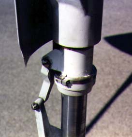
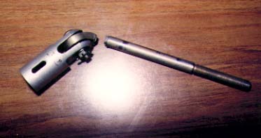
Rex Hume developed a minor problem with the nut of the nose gear working loose. Crude as it may sound, a good way to fix this sort of thing is to take a dull chisel and slightly deform the threads that the nut runs on. Rex decided to go the high-tech route and made this stainless steel collar which does the same thing. One thing about the dull-chisel method, it's certainly lighter and cheaper!
|
From "Construction Notes" Falco Builders Letter, June 1995 |
In the process of tweaking his Falco, Jim Petty has had a consistent problem with the landing gear circuit breaker popping on gear retraction. This doesn't happen on the ground, and by a process of elimination, Jim has come up with a very good theory about what is causing the problem. He thinks that at low speeds and full takeoff power, the swirl of air around the airplane causes the nose gear tire to turn as it retracts, the tire hits the screwjack and the system jambs.
As further proof, he has found that if the circuit breaker pops, once in level flight if he extends the gear part way and then retracts it again, it will jamb, but if he extends it fully (which causes the gear to straighten up with the rudder pedals) and then retracts it, it does not jamb. In recreating the problem on jacks, he finds that the system jambs with only a single turn left on the screwjack. Additionally, Jim says his nose gear swivels freely since he did not tighten the nut at the top of the trunnion.
I've been hearing about circuit breakers popping on Falcos for years, but it has always been a sporatic problem, and we have never be able to isolate the reason. For the first time, I think we can now understand what is happening and thus take corrective actions.
By far, the simplest solution is to tighten the nut at the top of the trunnion so that there is a moderate amount of friction in the steering action. That involves no additional parts, and no additional weight. The extra friction is not something you would ever notice while taxiing because you have an enormous amount of power in your feet.
Second, because of the pattern of the popping circuit breakers in the landing gear system, we should all develop a certain amount of paranoia for this and check the circuit breakers before extending the gear, or confirm that the landing gear has been extended when you select gear down. Perry Burholm recently had precisely this problem and landed with gear up because he did not notice that the circuit breaker had popped on retraction.
Perry thinks his problem was related to the gear-up limit switch and says that the mechanism that he devised to kick the gear straight (see page 11, 12/94 FBL) will work even if the landing gear is turned fully left or right before retraction.
Since developing this theory, Jim has since confirmed that the nose wheel tire is jambing because he is able to retract the gear without difficulty if he kicks the gear straight first.
Jim and I are going to put some think-time into the design of a mechanism that will straighten the nose gear on retraction. There are a couple of obvious methods of solving this problem, but I am inherently suspicious of complicated mechanisms. Bob Bready solved this by riveting two straps of stainless steel to the bottom inside of the cowling. There strips are about .75" wide and are made of the same material as the firewall. Bob bent the straps back onto themselves to make a vee-shaped spring. When the landing gear is retracted, the nose gear rocker arms hit these springs and kick the nose gear straight.
|
From "Construction Notes" Falco Builders Letter, September 1994 |
One part of the Falco design that's always been a bother is the down-limit switch arrangement. Frati's original design worked well on the production aircraft, but it's been very touchy on our Falcos. The reason is that the production machines all used a motor that would continue to turn after it was shut off. In other words, the motor would coast.
This permitted the down-limit switch to cut the motor off before the gear was fully down, and then the motor could continue to turn so that the screwjack would be driven into the spring. With our system, however, we use a permanent-magnet motor which has almost no coast at all. Builders report that the adjustment is very touchy, you have to hit it perfectly to get it right. Even then, most Falco owners give the crank an extra turn or two just to make sure.
We all owe Joel Shankle a word of thanks on this, for getting on my case, in his normal friendly way, about how touchy this is. Watching George Barrett getting his plane set up for the first flight caused Joel to start worrying about this down-limit switch thing and asked me to look into a redesign.
I remembered that Charles Gutzman had come up with an alternate way of mounting the down-limit switch, so I called him. His arrangement has turned out to be the best solution, and it's what a number of Falco builders have already done at my suggestion. Pure and simple, it's a far better way of handling things.
In this design, the down-limit switch is mounted on the aft face of frame No. 1, in the nose wheel bay so that the lever arm of the switch is directly below the screwjack. On the screwjack, you mount a clip. The clip is attached with one or two worm-type hose clamps, and at the bottom forward end, it has an arm that goes out from the screwjack by about 20mm.
George Barrett made the clip with a piece of tubing welded to a strip of steel. Joel Shankle machined a part out of aluminum. We will be makine a steel part that's stamped and formed to the tube. All of these designs are light and easy to make.
The beauty of this design is that it allows the gear to go completely down, start compressing the spring, and then it cuts off the motor. I worried that there might be so much coast to the motor that the coasting of the screwjack might damage the microswitch by exceeding its overtravel limits. Everyone says the motor stops "instantly" and that there is essentially no coast to the screwjack.
I mentioned this to Mr. Frati, who is using the same motor and gearbox design as we use on the Falco for his Penguino/Sprint aircraft, and they are going to do the same thing. (Don'cha love it, the great Frati building an airplane with a gearbox designed by the infamous Dr. Ing. Alfredo Scoti-a speech-and-drama major from drunken U.Va!)
From everything I can see, this design is a dramatic improvement over the previous design. At this time, we're working on new drawings for the parts and should have new parts available within a month or so. For those of you who want to make your own parts, go right ahead. If you can build an airplane, you're resourceful enough to make up something that will work.
|
From "Construction Notes" Falco Builders Letter, September 1994 |
If you ever need to replace the valve cores for the Schrader valves for the nose gear or main gear, John Devoe notes that the proper part is the 2300HV valve core listed in the Aircraft Spruce catalogue. My literature from Schrader calls it a P/N 2300TV, so one of these may be a typo.
|
From "Construction Notes" Falco Builders Letter, December 1994 |
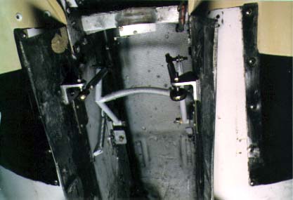
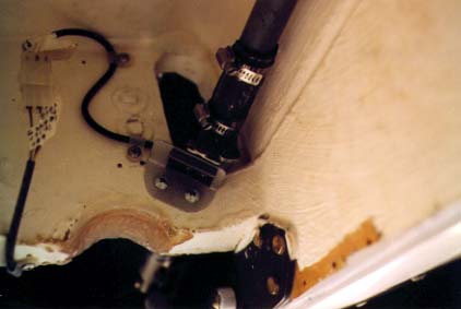
Perry Burholm has been making preparations for the Falco birthday party at Oskhosh '95 by working on his Falco. He wants it to look as good as possible, so he has been working on a better way to close the nose gear bay doors. The photos to the left show this mechanism, which is fully adjustable and will not open from air pressure.
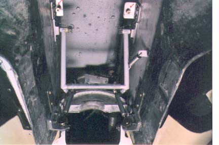
As mechanisms go, Perry's design looks to be reasonably simple and reliable. It's obviously heavier then the spring we have used, and involves greater cost if the parts were to be manufactured in quantity. On the other hand, it's several times simpler than mechanisms I've seen on a number of production airplanes from Wichita. I don't have any drawing on this, but if anyone is interested, perhaps we can get Perry to sketch it out.
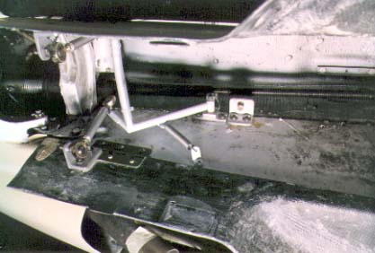
Just aft of the pivot points for the mechanism are two brackets with screws. These are used to center, or align, the nose wheel so the doors can close tightly. As I understand it, the screws hit the nose gear fork and kick it straight. And, obviously, the screws themselves are adjustable.
|
From "Construction Notes" Falco Builders Letter, March 1993 |
Guido Zuccoli and friends took their Falco for The Big Slide the other day. They were doing the last of the landing-distance tests for the Australian first-of-type approval. They had the warning horn turned off, and they're not exactly sure what went wrong. Even though they have the 13-second gearmotor, they were popping the circuit breaker 9 out of 10 times. They aren't sure if the circuit breaker had popped without them noticing it, or if they forgot to lower the gear.
The reason for popping the circuit breaker is a mystery to me. Even with full gear doors, the 13-second motor pulls the gear up with little strain on most Falcos. Something is clearly out of kilter on this Falco.
Guido said that if he had installed Steve Wilkinson's suggested landing skids, the airframe would not have been damaged at all. Instead, they suffered minor damage and will have the plane back in the air within a couple of weeks of the accident. The prop was a total loss, but as we have done so many times before we were able to find a Falco builder who didn't need this propeller right now. Al Aitken graciously came to the rescue.
|
From "Construction Notes" Falco Builders Letter, March 1993 |
When you are assembling the P/N 520 gearbox, there's a consistent problem with the lower miter gear on the vertical drive shaft not lining up perfectly with the gear on the horizontal shaft. Before you drill the hole for this gear on the vertical shaft, be sure to check to make sure it is going to mesh well with the gear on the horizontal shaft. Most don't fit right the first time, and you'll need to grind a little metal off the hub of the gear on the vertical shaft.
|
From "Construction Notes" Falco Builders Letter, June 1993 |
In our landing gear retraction gearmotor, there are a number of gears inside the case. Depending on the model, there are either one or two 'change gears', an assembly of two gears of different sizes on the same shaft. These change gears are made in the standard method of pressing one gear over a slightly-oversized shaft.
This is a perfectly acceptable way of doing it, however it is dependent on a tight fit. We've now had two cases in which the change gear has slipped. It first happened to Steve Wilkinson, who asked if there was an internal clutch in the gearbox that might cause it to slip. That was a couple of years ago, and then the other day, Jim Shaw reported the same problem.
I suppose it's likely that this minor problem will happen again. It's an easy problem to spot, and it will normally show up on the first retraction tests. It's also a very easy problem to solve. All you do is drill a 1/8" diameter hole so that half of the drill is cutting into the shaft and the other half is cutting into the inner face of the gear hub. Then you tap in a 1/8"Ø by .25" long dowel pin. This technique is referred to as a 'dutch pin' and it prevents the outer gear from spinning on the shaft.
|
From "Construction Notes" Falco Builders Letter, September 1993 |
Steve Wilkinson writes: "My main-gear shock struts continue to leak down slowly, one somewhat faster than the other, and never to the point where I'm dragging gear doors or anything. It's simply a matter of pumping them back up with my handy strut-pump every two or three months. I do wipe them clean and spray them with WD40 frequently, as you recommend.
"I mentioned this to Karl Hansen the other day, in a letter, and he replied that he had the same problem. I don't know if he's ever told you this, or how legitimate it is, but he thinks the problem is in the threading of the air fitting into the top of the barrel-that the drilling and tapping of that hole wasn't done micrometrically perfectly perpendicular to the barrel itself. So the air fitting doesn't seat perfectly flat. He recommends reaming those threads out a bit so that there's just enough thread-play for the fitting to seat perfectly flat.
"He points out that if the leakage were through the O-rings, there would be fluid leakage, and he doesn't have any. I don't either-not a bit. There's only the barest film of oil on the shiny part of the struts, barely enough to pick up dust, so I think the O-ring part of the mechanism is working just fine. (I think you'd also have fluid leakage if it were through a microscopic pinhole leak in the strut itself, wouldn't you?) Anyway, I think he may be right in that the problem is air leaking out of the struts independently of the oil."
Like you and Karl, I suspect that this very slow leakage is at the valve, but I don't agree on the analysis. We know that the surface finish of the metal that the O-ring seals against must be very smooth, and we have a little tool that we have sent to many builders to smooth this out with valve grinding paste. I've always heard that it's a good idea to put a light grease on the O-ring before you screw the valve into the strut, and I suspect that very slow leakage is less likely to happen if some grease in there. Finally, I called Schrader, the manufacturer of the valves and asked if they had any suggestions. An engineer said it sounded to him like the swivel nut was not tight enough. You have to loosen this nut to put pressure into the valve, and when you are through the swivel nut should be tightened to at least 60 inch/lbs. (He also mentioned that the valve core should be tightened to 3-5 inch/lbs if you want that bit of trivia in your brain.) I suspect that the answer to the very slow leaks is more than likely to be caused by one of these things.
On the other hand, Cecil Rives has also had very slow leaks with both of his struts, and finally brought one home and put it in a sink full of water for the night. In the morning, he noticed that there was a series of tiny bubbles around the joint between the P/N 553 oleo cylinder and P/N 554 oleo nut. Cecil wrapped some Teflon tape on the threads of the nut and reports that the leaks have stopped.
I doubt, however, that the Teflon tape will prove to be a long-term solution, because if the O-ring is leaking it will continue to leak until enough pressure builds up to overpower the Teflon tape. O-rings typically leak because they are abused, as in the case of being cut on threads in the assembly process. The surface finish of the mating surface is also important. I've checked some cylinders we have here and the surface finish appears to be very smooth, but if you have a problem you can smooth it out with a ScotchBrite pad or very fine emery paper.
I find it curious that it is leaking air when you would expect that oil would leak for this location. I know that one of our earliest builders reported that he had a problem with a leak in this place until he completely filled the cylinder with oil and then screwed the oleo nut in place.
It's also possible that the O-ring is not being squeezed enough. I have double-checked the tolerances of the O-ring grooves, and it appears that the groove may be slightly too deep. In checking the tolerances against my O-ring manual, it appears that the ideal groove would be 1.519"Ø, +.000" .002" with a groove width of .146". +.010", .000". There's ample room for a new groove if any of you have a lathe and want to experiment.
A far cheaper and easier way of trying to get more rubber squeezed in there would be to go to a larger cross-section O-ring and stretch a smaller diameter O-ring in place. I've experimented with various O-rings, and I find that a MS28775-215 O-ring looks about right. We'll get some of these into the hands of builders who are having very slow leaks and see if it stops the problem.-Alfred Scott
|
From "Construction Notes" Falco Builders Letter, September 1993 |
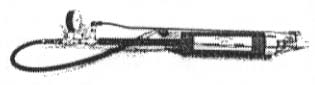
Here's the 12X strut pump that Stelio Wilkinson uses. Hooked to an air bottle or air compressor, you hand-pump it to deliver 12 times the pressure of your source. It's available for $329.00 from Bogert Aviation, Rt. 1, Box 1676, Presser, WA 99350. Telephone: (800) 627-8088, (509) 786-4004 or fax (509) 786-4300.
|
From "Construction Notes" Falco Builders Letter, December 1993 |
In the last FBL, we discussed the problem a few builders where having with the O-ring in the main gear shock absorber strut, and the possibility of using an MS28775-215 O-ring. Since then, Allan Hall, has tried this O-ring and reports that the leaking problems have disappeared.
|
From "Construction Notes" Falco Builders Letter, December 1993 |
Jim Slaton reports that at 700 hours on his Falco, he had a problem with the nose gear rocker arm on the top of the nose gear strut. The hole for the bolt became ovalized, and he cured the problem by using a 5/16" bolt. John Harns had the same problem at the same number of hours on his Falco, and he used the same fix. They both think the wall thickness of the tubing for the rocker arm is too thin.
|
From "Construction Notes" Falco Builders Letter, December 1993 |
At Oshkosh, Bjoern Eriksen-who everyone knows is meticulous-pointed a stern finger at the nose gear retraction system and told me that the use of steel bolts in the aluminum drag struts was a bad idea, that it would wear with time and would cause problems. I asked Jim Slaton, who now has about 900 hours on his Falco, to take a look at this. Jim reported that there was quite a bit of slop in the nose gear linkages, but that the holes were not egg-shaped. He had a local machinist install thin-walled steel or bronze bushings. While this doesn't worry me greatly, this is something we should all watch.-Alfred Scott
|
From "Construction Notes" Falco Builders Letter, March 1992 |
We've had a couple more problems with the landing gear. Steve Wilkinson took off in a crosswind and then was unable to retract the gear. He landed without difficulty and found the right main gear screwjack was bent very slightly. It was exactly the same thing that had happened to Jim DeAngelo some years ago, and neither Steve nor I could figure out how it could have happened.
The only way the gear could have folded was if the side load struts did not go over-center, and the kick test will prevent that from happening. "Did you do the kick test?", I asked. "Oh, sure," said Steve. "Did you have the screwjacks removed from the side load struts when you did the test?" "Well, no..." Oh dear.
After talking it over, it was quickly apparent what the problem was. Steve had not understood that the kick test was supposed to be done with the screwjacks disconnected. The idea is that the side load struts should be adjusted-you just file on them-until they go slightly over-center. The best way to find out if they are truly over-center is to press hard on the tire with your foot (you really don't need to kick) and see if the side load struts will stay locked without assistance from the screwjacks.
If they're not quite over-center, as was the case with Steve's Falco, they fold very easily. You're just asking for trouble if you don't do the Kick Test with the screwjacks disconnected, and Steve asks that I emphasize this point. As it turned out, he was able to remove the screwjack and bend it straight again.
And Jonas Dovydenas had a problem of a type I've never heard of before, nor has anyone ever speculated on it. He took off one day, and flew around for a while. On approach for landing, he lowered the gear and something was definitely not right. Initially, Jonas was very confused about what had happened. The gear went partially down and then there was a 'clunk' sound. The nose gear was down, and there was a green light that the gear was down. But Jonas still was able to crank the gear about 5 more turns down.
He landed without incident, and after he shut the plane down, he was surprised to find that the nose gear screwjack was completely disconnected from the nose gear upper drag strut. The long custom rod-end bearing was broken off at the top.
It didn't make sense to me how that could have happened. When the gear is down, that bearing only has about 40 lbs of side load on it to keep the gear down. That's nothing, and when the gear is fully up, there's about 700 lbs of tension on the screwjack when you do a 6-g loop, but the rod end bearing is lined up with the screwjack. That puts it all in tension, and the part is certainly more than adequate for that load. It was a real puzzlement.
But when Jonas took it apart to put in the new pieces, it was abundantly clear what had happened. There's a jamb nut at the base of the bearing, and this had been working loose. When the gear came up and the screwjack was lined up with the rod end bearing, the torsion of the landing gear motor was starting to turn the rod end bearing. The shaft of the rod end bearing showed clear signs of rotating in the upper drag strut (see photo).
What had happened was that each time Jonas retracted the gear, this thing would turn slightly, then turn back straight again when the gear was extended. Each cycle would loosen the jamb nut a little more. Finally, it reached the point that it had turned completely horizontal, so that when the gear was extended, the thing was turned completely sideways.
This problem would not happen, obviously, if the jamb nut is tight. Everyone should check this on their Falcos and tighten the nut down snugly. You can also put a little dab of red paint on the nut at its base. This is a standard method of marking a nut so you can see at a glance if the nut has moved because the paint would be cracked.
|
From "Construction Notes" Falco Builders Letter, March 2000 |
Jacob Brouwer reported that he experienced the same difficulty with his landing gear that Jonas Dovydenas earlier reported. In Jonas's case, the nose gear adjustment rod, installed in the nose gear upper drag strip, turned 90° on retraction and bent at right angles when he selected gear down.
In Jacob's case, the bending was not as severe, and he reported that the rod was bent about 20°. This required replacement, and Jacob commented that he had the nut tightened down tightly, or so he thought, but he had not installed a roll pin to prevent the rod from turning. You can be sure that the new adjustment rod will be properly safetied this time with a roll pin, and for those of you who haven't taken this safety step, well, your day could come soon.
|
From "Construction Notes" Falco Builders Letter, June 1992 |
In the brake system, we use a little piece of brass tubing shoved into the nylon tubing so that the metal fittings can tighten down on the tubing. This makes a superior joint, but I'm told that the 1/8" tubing that we supply is a little loose in the 1/4" nylon tubing. I suggested to Cecil Rives that he get some 5/32" brass tubing at a model airplane store. It wouldn't quite go in, but he found that if you heat the tubing, the brass insert will go in and the tubing will still fit in the Swagelok fitting.
|
From "Construction Notes" Falco Builders Letter, September 1992 |
John Harns now has about 750 hours on his Falco, and recently noticed that the nose gear rocker arm (P/N 663) was moving slightly on top of the nose gear. After taking it off, he could see that the hole for the 3/16" bolt was slightly ovalized. He replaced it with a 1/4" bolt. Jim Slaton has the same number of hours on his plane, and after hearing this report, he pulled his off and found the same phenomenon-which is called brinnelling if you want to sound educated.
I suspect this is something we will see more of. While hardly serious, this sort of thing can be cured by using a larger bolt, welding a washer on the outside of P/N 663 to increase the bearing area of the bolt in P/N 663, or by using a taper pin. Larger bolts are certainly easier.
|
From "Construction Notes" Falco Builders Letter, September 1992 |
Pawel Kwiecinski recently had a problem with the nose gear. He now has about 250 hours on the plane and the other day, when he retracted the gear, it wouldn't come all the way up. The circuit breaker popped, and then he had to crank it about ten more turns to get it up.
Later when he put the gear down, he had additional problems, and had to crank it again. On landing, he found the nose gear screwjack end and the nose gear adjustment screw were both bent-to one side as you looked at it from the front and with the gear down. After talking to Pawel, it was evident that the same thing happened to him that also happened to Jonas Dovydenas (see March 1992 FBL, page 14).
Pawel said that he had read about Jonas's problems, but hadn't checked his airplane. Other than a couple of bent parts which needed to be replaced, there was no damage to Pawel's airplane, but it's quite clear that this syndrome will repeat itself with regularity if you do not tighten the nut tightly and check it often.
The little dab of paint that you put on a nut like this comes in a tube and has the delightful name of Torque-Seal Inspector's Anti-Sabotage Lacquer. All of the mechanics at your local FBO will have a tube. They get it from Aviall. I've never noticed it on any of the homebuilder's supply catalogues.
Another place to put some Anti-Sabotage Lacquer is on the big nut on the nose gear. Jonas Dovydenas had this loosen on him with the result that the O-ring was ruined.
|
From "Construction Notes" Falco Builders Letter, September 1992 |
I flew in formation with Steve back in August, and took a look at his gear doors. The main gear doors seem to be pulling open about an inch at the outboard trailing edge. The doors themselves are exceptionally stiff, and we think this is being caused by some movement in the linkage itself.
I was also surprised to see that the left nose gear bay door was fully open. Steve checked this out, and found it was a problem with the wooden block he had installed on the spring. Many builders have found that it's a good idea to clamp a wooden 'saddle' at the top of the spring in the middle. This takes care of all adjustments of the spring, because rather than trying to get things right by bending the spring, you can just make the spring tool long and use a wooden block clamped around the spring. The adjustment is accomplished by sanding the block to a shape to fit the nose gear cylinder.
I think Ray Purkiser was the first to use this device, and it's a good idea. Ray's is made of hardword and works well. Steve's was made of spruce, and this turned out to be the source of the problem. The spruce is simply too soft for this application. The groove that the spring was trapped in became sloppy, and the block had shifted out of place. Steve replaced this with a phenolic block.
|
From "Goings On at Sequoia Aircraft" Falco Builders Letter, December 1992 |
In the last newsletter, I discussed the problem with the nose gear control arm sometimes spinning in the upper drag strut, the big 'A-frame' casting in the nose gear retraction system, and the need to keep the nut tight. Mr. Frati advises that this problem also occurred on the F.15 Picchio, and it was solved by installing a pin to prevent the P/N 605 nose gear adjustment screw from turning by friction with the screwjack. After the entire system was set up and all rigging had been completed, they drilled completely through the casting and through the shaft of P/N 605 and installed a roll pin.
A 1/8"Ø x 1.125" roll pin is perfect for this, and according to my calculations it should be located about 40mm above the base of the casting. We will be adding this to the retraction kit, and we'll get a revision or new drawing out at some time. In the meantime, those of you flying, and with the system all set up, can go ahead and install one of these roll pins to safety the part in position.
|
From "Construction Notes" Falco Builders Letter, March 1991 |
Stephen Friend also reports, "After reading about builder's difficulties assembling the retract gear box, I was congratulating myself about how well I had got the vertical shaft running against the forward mitre gear-nicely against the top and bottom bearings, no binding or backlash. Then I tried to assemble the mitre gear on the bottom shaft. The bottom mitre of the vertical shaft appears 4mm too low. The lower bearing is holding the miter gear 2mm below the housing but is itself correctly seated in place. Do I take 4mm off the top of the mitre gear and will the vertical shaft take being cross-bored for the roll pin?"
We've had some other builders report similar difficulties. It's really a good idea to look one step ahead and make sure each gear will mesh nicely with its mate before committing yourself with a drilled hole. It's quite all right to sand or grind material off the hub of the lower miter gear to raise it up to mesh with the miter gear on the horizontal shaft. Best to do that before you drill any holes, but if you have to cross-drill the shaft, then that's all right, too.
|
From "Construction Notes" Falco Builders Letter, June 1991 |
When installing the universal joints on the shafts of the retraction system, Nick Broussard was confused by the tiny holes already drilled in the universal joints. He thought that perhaps they might be pre-drilled pilot holes for the taper pins-but they seemed to be so poorly drilled, way off from where they should be.
Oh dear. This is one of those little things that people in the business take so much for granted that they forget that others don't know about them. The little holes are called 'witness holes' and you find them on univeral joints, certain types of rod-end bearings, and other devices that are intended to be installed over a shaft. The witness hole is simply an inspection hole so that you can peek in and see that the shaft is inserted all the way in. That's all it is, just an inspection hole.
My main gear oleos are soft compared to others.
According to sheet F1, draw no 601, Nose gear oleo is filled by " - - pumping up and down until air bubbles cease to be expelled. Push lower cylinder fully up and remove hose." Presumably, insert the valve core when the cylinder is fully up, then inflate to 115 psi.
Your revision E6b, for main gear assy says: Remove valve and add oil thro hole until oil spits out of opening when strut is compressed in vertical position. Inflate to 600 psi
The aircraft should be jacked up when filling oleos. I assume, like the nose oleo, the air should be expelled as per the nose oleo instructions, and with the oleo fully compressed insert the valve core. With cylinder compressed, ( don't let the weight of the wheels decompress the oleo) inflate to 600 psi.
By leaning on a wing tip I get a much greater movement in the oleos than either Stuart or Neville whose struts are comparatively rock hard. Stuart admits he inflates to higher than 600 psi.
Could you comment.
Charles Wagner
As you get older, your oleos get softer. Ignore the pressure specs, particular on the mains, and pump them up till they feel right.
Alfred
Forget my last letter. After messing with them today I found that I had not got the oleos full enough of oil and overfilled them with N2. The reason, I think, is that I did not understand how the Schraeder valve works. I still don't but the oleos are fully up and feel quite firm.
Just read your reply. They have banned the wonder drug here from the National Health service. As I said, there is nothing wrong with the oleos, it's the old fart filling them.
Charles
|
From "Construction Notes" Falco Builders Letter, September 1991 |
The big problem with Steve's Falco, of course, was the gear-up landing that it suffered on the way home from Oshkosh. The accident occurred on July 27 at Hanscom Field, near Boston, Massachusetts at approximately 9:30 at night. The pilot was Mark Reichen and a friend, Jeff Jones, was the passenger. Neither were injured.
Subsequent investigation showed that the aircraft was landed with the gear up because of a seized screwjack to the left main landing gear. Mark Reichen remembers selecting gear-down, but admits that he doesn't remember seeing a red gear-in-transit light or a green gear-down light.
The propeller blades were both curled, but damage to the aircraft was minimal. The weight of the aircraft was carried on the nosewheel and the flaps. The inboard end of the right flap spar was torn from the flap. The fairing for the right side load strut was scraped, as was an area of the bottom of the fuselage.
The aircraft was placed on jacks and all attempts to lower the landing gear with the motor and hand crank failed. The mechanic removed the left main screwjack sleeve/screw/universal joint combination from the airplane and was able to break it free by putting a screwdriver in the taper pin hole and cranking over on it. The screwjack released with a 'snap' and then turned easily by hand. The mechanic reported that there was plenty of grease on the screwjack, and later also mentioned that there seemed to be grease on the end of the screwjack as well.
This accident reveals a mode of failure that we had not considered before and which could result in other seized screwjacks with any of the Sequoia Falcos. There are several factors to consider:
1. The best bearing surfaces are with two metals with different hardnesses and ductility. This is the reason for using bronze against steel bolts in the hinge system of the Falco, and for using bronze against steel in this screwjack system.
2. The screwjack sleeve is made of .75"ODx.049"wall 4130N steel tubing and when it bottoms out, it will contact P/N 623 bushing inside the universal joint. Some of the contact will be bronze-against-steel, which is desirable, and some will be steel-against-steel, which is not desirable and (now that we are thinking about it) is conducive to seizing if no lubrication is present. If you calculate the diameter of the screw, it works out to 1.57" and with 10 threads per inch, this results in a 1.57"-wide by .10"-high wedge. That's a 1/15.7 slope or 3.64° wedge that is jambed.
3. When a screwjack is turning and then bottoms out against something, the inertia of the rotation will greatly increase the torque of the motor. With this system making 100 turns in 7 seconds, the rpm is above 800. I'm told that the increase in torque from this inertia is 7 to 10 times, at a minimum.
4. The greater the diameter of the contacting faces, the greater the speed of the contacting metals, thus there is a greater tendency to gall the metal. Indeed, you can actually weld pieces this way-it's called friction welding. We would not be getting into the heat required for welding here, but you see the point of a greater diameter increasing the tendency to seize.
5. Moly grease is used for screwjacks because the particles of molybdenum disulfide act as little ball bearings. Under a continuous load, the grease would squeeze out. The particles of moly prevent a total squeeze-out. When the part starts to turn again, the particles act as tiny ball bearings until grease starts to smear over the part. The moly particles prevent seizing for this reason. Moly grease is good stuff, but it is not such a miracle product that it could prevent steel-against-steel seizing.
We believe that the screwjack seized at the steel-tube-against-steel-bushing interface because of steel-against-steel contact. Mr. Frati agrees with this as the cause of the seizing. He is adamant that the screwjack should never bottom out against the bushing and that the limit of the gear-up travel be determined by contact between the main gear leg and the wing structure at Sta. 1 and by contact between the nose gear and fuselage frame No. 1. Mr. Frati recommends a minimum distance of 3-5mm between the end of the screwjack and the universal joint to prevent screwjack seizure under any conditions.
To keep this from happening again, we recommend:
1. Shorten the screwjack sleeve so that 3 to 5mm of clearance exists between the end of the screwjack sleeve and the end of the universal joint when the landing gear is in the fully "up" position. If the screwjack sleeve is shortened by sanding, completely clean the screwjack with solvent to insure that all sanding grit is removed.
Note that all ground retraction tests will be with 12 volts while the 14 volts of the electrical system will cause the motor to run 17% faster (the motor speed is directly proportional to the voltage) and thus will coast slightly more. For this reason, we suggest that you do not rely on a few thousandths of an inch clearance as adequate.
2. For any installation where a minimum of clearance exists (i.e. less than 3mm), we recommend: (a.) Lubricate of the end of the screwjack and the bushing in the universal joint with Aeroshell 7 grease-the same moly grease used on the screwjack. (b.) Chamfer the end of all screwjack sleeves (preferably with a file to keep sanding grit from getting in the screwjack nut) so that the screwjack will bottom out with bronze against steel.
By the way, Mark Reichen was sweating bullets over being cited by the FAA for flying the Falco out of the practice area prematurely. With about 46 hours on the plane at the time of the accident, anyone who could add could figure out that he must have left for Oshkosh before the required 40 hours were flown off. When he finally turned up with the log books fully prepared to stonewall and say nothing that might incriminate him, the FAA inspector blew up when he found the restriction in the logbook, not at Mark but at the in-training Teterboro inspector who wrote the silly thing in the logbook in the first place. The Teterboro guy clearly didn't have the slightest idea what he was doing, tell him so for me, and haveaniceday.
|
From "Construction Notes" Falco Builders Letter, September 1991 |
Charles Wagner had a number of questions on the wheel well doors. First, he asks for confirmation that the doors should be made of 3 layers of glass top and bottom-6 layers total. That's right. Second, he asked for the reason for the long rivets. Answer is that I don't remember the reason for the rivet length, but it's almost certainly an attempt to give you a rivet that is at least long enough to accommodate the thickness of the fiberglass-which I was unable to know with any certainty. You should always cut such a rivet off so that it sticks up by one-and-one-half diameters above the surface before driving it. Finally, he asks if washers should be used under the head of the rivet when riveting fiberglass. No washers are necessary. With fiberglass, you should always use soft "A" rivets of pure aluminum, rather than the harder alloy "AD" rivets normally used in aluminum sheet metal structure.
|
From "Construction Notes" Falco Builders Letter, September 1991 |
Couple of notes on the construction manual. We get questions about the torque tube that connects the nose gear screwjack to the gearbox on the aft face of the spar. We've made a change in the tube where the tube connects to the universal joint at the aft end. Originally, this tube had ends on it which reduced the diameter down to 1/2".
We use a 3/4" universal joint and have to step it back up to 3/4" with a bushing. Because the torque tube is already 3/4", we no longer put a step-down end on the tube, instead we weld a piece of tubing inside to increase the wall thickness of the tube and insert it directly into the universal joint with any bushing at all.
It will all be clear to you when you put it together, and the new method is lighter, cheaper and simpler than the old method. The only thing you need to remember is not to Loctite a bushing in this universal joint, because you don't need a bushing there at all.
|
From "Construction Notes" Falco Builders Letter, June 1990 |
Terry Smith reports that he made a new set of main gear wheel well doors. These doors are flatter and have a hinge with the bulb slightly out in the air. Terry doesn't know which of these things made the difference, but these doors work much better and the gear will come up all the way most of the time. When the circuit breaker does pop, the crank only takes another 1/4 turn.
Terry reports that is consistently getting 165 knots indicated in normal cruise and often sees 2000 fpm on the VSI when lightly loaded and by himself.
|
From "Construction Notes" Falco Builders Letter, September 1990 |
Steve has also been struggling with the nosewheel tire: "After having gone through three nosewheel tire tubes during the course of construction, I have concluded that the tire-installation instruction in the manual are not the way to go. Covering a tube with talcum, dishwashing detergent or whatever else is a fine way to mount a conventional tire, but it simply doesn't work with a split-wheel mounting. My technique had been to inflate the tube enough to get it snug in the tire, deflate it by taking out the valve core and then mount the tire/tube assembly on the wheel using dishwashing soap as an anti-pinch aid. Three out of four tries, it didn't work, and the tube got nibble to death by the knife-edged split between the two wheel halves.
"Now I've tired a new technique, and it works perfectly: Namely, leave the tube in its totally flat, totally uninflated state, as it comes from the supplier (or suck the air out of it somehow to achieve the same flatness) and the put it into the tire, valve stem properly located, and assemble the wheel. In such a flat condition, the "inside diameter" of the tube is considerable greater than the diamter of the wheel-seam, and there's no chance of pinching and no need for talc or soap in any case."
Hmmm. The method we suggest is pretty much the standard method used by mechanics and in that method the tube is inflated enough to round it out but not so much that it starts to expand. This makes it difficult to pinch, and I've used the method without difficulty. Dunno where Steve got the notion about deflating the inner tube unless he misunderstood our instructions about doing this after the wheel is assembled. The normal procedure is to inflate the tire and then completely deflate the tube to remove any folds that may have occurred in the tube.
|
From "Sawdust" Falco Builders Letter, September 1990 |
England's foremost Falco expert, Andrew Brinkley, says that he's discovered that a tire made by Tost Aero in Germany fits the production Falco's nose wheel. This tire-dunno the exact size-is used on high performance sailplanes.
|
From "Construction Notes" Falco Builders Letter, December 1990 |
Steve Wilkinson reported an unusual problem with his landing gear motor. In running the gear up and down with the plane on jacks, the landing gear motor would bring the gear up almost all the way, and then the gear would stop moving while the motor continued to run. He asked if there is a clutch in the system, and I assured him there was no such thing. But then I remembered how the gearbox is assembled, and I realized what his problem was.
Our gearbox is something that I designed after studying how the original Falco system was made-it was a surplus bomber flap gearmotor that had been kludged into a landing gear motor-and also by using drawings of Frati's current motor arrangement. I had also taken apart a number of electric hand drills to see how they are made.
They all use the same method of making change gears. A length of pinion wire-dunno why they call it wire because it's a 5/8"Ø shaft machined with gear teeth on its entire length-is machined down for 1/4" shafts for needle bearings and there's a shoulder turned on the gear and then a larger gear is pressed onto that shoulder.
It all works because it's a tight interference fit, and the pressure is enough to keep the outer gear from turning on the inner gear's shoulder. On Steve's system, the fit was not tight enough and one of the gears was slipping.
There's an easy fix for this. All you do is drill a 1/8"Ø hole at the junction of the two gears and parallel to the axis of the gear shaft. This means that half of the hole is in the outer gear and half in the shoulder of the inner gear. You then tap in a 1/8"Ø dowel pin and put it back together. The dowel pin prevents the gears from spinning any more. This type of thing is called a 'dutch pin' and you can use a setscrew instead of a dowel pin.
It's unlikely any of you will have this problem, but if the symptoms of this little malaise show up in your Falco, that's what the problem is. If you need a dowel pin, just let us know.
|
From "Construction Notes" Falco Builders Letter, September 1989 |
Jim Slaton has had continuing problems with his gear doors and the gear retraction system. He got everything adjusted so that it worked perfectly when the airplane is on jacks, but once he got it in the air, the system would start to act up on him. The gear would retract all right, but the circuit breaker would pop with just a turn or two left left.
The first thing that anyone starts to blame is the gear motor. It's a logical conclusion: the motor's too small, or the gear ratio needs changing. I asked Jim to watch the load-reading ammeter to see how many amps the gear motor was pulling. The motor that we use has a no load speed of 5350 rpm at 2.7 amps, pulls 61 amps with a locked rotor pulling 172 oz/in, and an operational speed is considered 4260 rpm at 35 oz/in torque at 14.6 amps. All those figures are for 12 volts, and there is a linear relationship between voltage and speed, and voltage and stall torque.
What all this comes down to is that if the motor pulls less that 10 amps to raise the landing gear, the motor is barely being strained. Our motor turns 7.031 turns for every turn of the screwjack, and it takes 100 turns of the screwjacks to raise the landing gear. For those of you who know how to construct a power curve from this data, you can see that if our gear comes up in around 7 to 8 seconds, the motor is correctly geared and it barely working.
This is what Jim Slaton reported and that the current draw of the motor during the retraction was hardly worth mentioning, rising slowly to peak around 7 amps or so, but then the amps would spike and the circuit breaker would pop. Folks, the motor and gear ratio is fine. It has to be something else.
Jim also reported a number of other things that didn't add up to me. He reported that if he cranked the gear up the last turn and then reset the circuit breaker, the breaker would immediately pop again. I concluded from this that his up limit switch was not closing. The strange thing was that it all worked perfectly on the ground, but not in the air.
We don't use a gear up light in the Falco, but it's quite easy to hook up a wire to the NO (normally open) terminal of the up limit switch, run this switch to an indicator light and ground the light. Wired this way, the indicator light would immediately indicate when the up limit switch is closed.
This is where I left Jim before Oshkosh (which seems to take a month out of things). I talked to Jim the other day, and he reports that the problems have all be straightened out. Jim said the up limit switch was closing properly, and that the problem was something to do with the adjustment of the linkage to the main gear wheel well doors. I can't explain why the circuit breaker continued to pop when the gear was cranked fully up if the up limit switch was closed. It makes no sense to me at all.
|
From "Construction Notes" Falco Builders Letter, September 1989 |
Terry Smith was also having some problems with the landing gear system and the doors. He finally traced his problem to the nose gear turning during retraction so that it hit the screwjack. Terry made a guide from wire and nylon tubing that prevents the tire from hitting the screwjack.
Over the years, I heard a lot of people worry themselves sick about this, and I've always told people not to worry about it because I've always thought that this was one of those things that is theoretically possible but so unlikely that it would never happen. Most Falcos have the nut tightened down enough on the nose gear so that it does not rotate easily in the trunnion. I think this is the desirable condition and even though it might be stiff to turn in your hands, you exert a lot of force with your feet and would never notice this when you steer the plane.
With some friction in the system, the nose gear does not turn as it is retracted, thus the only way you can jam the gear is to take off, push full left rudder (an incredibly violent maneuver) and then retract the gear. As a practical matter, you'll have a little right rudder when you select gear up. I think the solution to all of this is simply to tighten the nut on the top of the nose gear until it's a little stiff. Then don't worry about it.
|
From "Construction Notes" Falco Builders Letter, June 1988 |
Here is Richard Clements's description of how he made the wheel well doors:
I laid a large piece of paper over the opening with the gear inside and the aircraft upside down. I traced the sides of the opening and located the center of the wheel axle. I also drew radials 10° apart from the wheel center and measured the highest point along the radials that the tire extended above the skin. Next, I took the gear out of the well and inserted 3-inch thick foam. I laid the paper on the foam and inserted 2-inch finishing nails through the paper into the foam at the high points on the radials. The reason for the nails was to locate the high points during sanding of the foam. As I sanded, I would push the nails down farther into the foam so as not to lose their location.
Finally, it was merely a matter of sanding away the foam to the desired shape using the nails to determine how high above the fuselage skin the door needed to be to clear the wheel. I applied the fiberglass directly on the foam with West System epoxy. There are three layers of 10 oz. glass on the outside. The foam stuck to the fiberglass and no attempt was made to remove it. Instead, it was shaped to form the inside contours and three more layers of 10 oz fiberglass were applied.
Richard Clements
Richard also said he was not at all happy with the way the hinges of the doors came out since he had to sand on the fuselage for clearance. He found you could make things easier for yourself if you reverse things so that the bulb on the door's half of the hinge is to the outside of the airplane, while the other half of the hinge is in the normal orientation. This only moves the center of the hinge about 3mm, but that makes a real difference on how much you have to sand on the airplane.
|
From "Construction Notes" Falco Builders Letter, December 1988 |
Steve Wilkinson asked about the proper procedure for setting up the retraction for the nose gear. In the construction manual, we already have the procedure for getting the main gear screwjacks properly synchronized with each other. What you must do on the nose gear is this:
First, crank the main gear down so that the screwjacks are fully extended but not yet pushing on the springs. The best thing to do is to take the nuts off the bolts and turn the crank until you can just slide the bolt in.
Second, adjust the height of P/N 605 Nose Gear Adjustment Screw to a height of 127mm as shown in the sketch below right.
Third, screw the nose gear screwjack into the screwjack sleeve. Install the rod end fitting and spring, and then bolt all of that to the nose gear adjustment screw. Turn the screw out until it fits into the universal joint. Then drill for the taper pin to fix the screw in place. This will properly synchronize the system.
|
From "Construction Notes" Falco Builders Letter, December 1988 |
Buzz Glade reports that he found the tires for the 5.30x6 wheels available from Carlisle Tire & Rubber Company, P.O. Box 99, Carlisle, PA 17013. Telephone (800) 233-7165 or in PA (800) 222-1876. They carry the tires in 6-ply rating and call them a 5.30/4.50-6 tire with sawtooth thread. Buzz says the 4.10/3.50-6 tube will fit, will not pinch, has the right valve stem and is easier to obtain. These tires are always available from Desser Tire and Rubber Company per our listing in the price list.
|
From "Construction Notes" Falco Builders Letter, December 1988 |
As builders approach the completion of their Falcos, they get their main gear struts pumped up. Most aircraft struts are pumped up with high-pressure nitrogen bottles. Most FBOs have such a bottle and can easily put the required pressure in the struts. Unfortunately you will find that you will not be able to get exactly the right amount of air in the struts until you have the aircraft on the gear. Taking the struts to the bottle will not do.
The reason is that you will inevitably find that you need just a little more pressure than the 600 psi specified. My Falco usually ends up around 650 psi. Frankly, I regard the 600 psi as a rough guide. I crank the handle on the regulator until about 600 psi is showing on the gauge. Then I bounce the wings of the plane to see how it feels. I add enough so that the struts are fully extended with no one in the plane and so that they will still compress when you lean on the wing. Imprecise perhaps, but that's what everyone ends up doing.
|
From "Construction Notes" Falco Builders Letter, June 1987 |
Drilling the Gears in the Retraction System. Despite my best efforts, when I drilled that shaft for the spur gear at the top, it somehow moved very slightly out of alignment-I can hardly believe it, it was so tightly secured-or the method of attaining gear-meshing by using a strip of grocery-bag paper, mentioned in a recent builder letter, didn't work for me.
Anyway, after all that effort, it seems to me the proper assembly technique ought to be to simply assemble and clamp the shaft so the miter gears in the box fully mesh (i.e. mesh slightly too tightly), then drill for the roll pin through the spur gear and shaft, then shim the spur gear (with AN960-816L washers) for the perfect mesh of the miter gears. This will spare builders a lot of worry about achieving and maintaining critical mesh before drilling, and a lot of hassle involved in clamping, securing, locking and building some kludge that's impossible to wrestle onto a drill-press table.
This will also give a better mesh of the spur gear with the retraction motor gear, if that matters. The method suggested in the manual (i.e. mounting the spur gear so that it rides "snug against the bearing" in the box framework) actually can't be achieved: what you get is the spur gear riding tightly against the milled upper surface of the box framework, since there's no shoulder on the inside "bottom" of that spur gear to ride against the bearing. That doesn't seem to me entirely right, and by shimming the shaft and gear slightly-even though it's the mark of a "misdrilled" roll-pin hole-you at least get the spur gear up off the box framework and into full mesh with the motor's drive gear.
Steve Wilkinson
Steve's problems with the spur gears are because a few spur gears were made without the shoulder on the "bottom" side. This is a perfectly usable gear but requires an AN960-816 washer as a spacer. I thought we had caught all of those. If you have such a gear, drop us a note, and we'll send you a washer.
Alfred Scott
|
From "Construction Notes" Falco Builders Letter, June 1987 |
Fire Protection for the Nose Gear Bay
At various places in the construction manual, I mention lining
the nose gear bay with stainless steel. This was done on the production
Falcos, although the nose gear bay cover was aluminun.
It's difficult to say where the firewall should stop, but in the event of an engine fire some flames would enter the nose gear bay. The idea of a firewall is to get you back on the ground without scorching yourself. The nose gear bay, then, is a proper candidate for some sort of fire protection, but stainless steel is probably an impractical solution for most builders. Stainless steel would do a good job of protecting the wood, but would do nothing to protect the fiberglass nose gear bay cover-the weak link in the chain.
You could use Fiberfrax ceramic paper to line the nose gear bay cover, but I think a more practical solution would be to use one of the flame blocking paints that have been recently developed. These paints look like a dull house paint but at about 200°F they blister up into a foam and this foam gives relatively good protection. I don't have any exact brands to recommend to you right now, but I know that Wicks sells a paint of this type. Quickie Aircraft used to sell "Liquid Firewall", which I understood to be a Fiberfrax-like ceramic insulation slurry in a paint. As this is Steve Wieczorek's department at Sikorsky, he is going to look into this.
|
From "Construction Notes" Falco Builders Letter, June 1987 |
Nose Gear Steering
I continue to get questions from builders about the function of
the little bronze rollers on the
nose gear steering arm. Builders
put all of the pieces together and then are surprised to see the
roller below the rocker arm on the top of the nose gear. This
is correct. The rollers do not contact the rocker arm when the
gear is down.
The rollers are there only to align the nose gear when the controls are crossed up. If you put in full right rudder while selecting gear up-and later hold full left rudder when you lower the gear-the rollers will kick the nose gear straight. It is a devilishly clever device and the best way to understand it is to watch it in action.
I also hear from builders who worry about the possibility of jambing the nose wheel tire against the nose gear screwjack. It is true that if you select full left rudder when you select gear-up, the tire will hit the screwjack, and this will cause the circuit breaker to pop. (It is also true that if you put your foot through the windshield, it will break!) Because this will only happen as a result of a deliberate attempt to screw things up, and because a popped circuit breaker is hardly anything to be concerned about, you don't need to do anything about this.
And before you fix this "problem", get a ride in a Falco and try stomping full left rudder. The Falco has a powerful rudder! You will have a hard time finding a Falco pilot who would sympathize with the "problem".
|
From "Construction Notes" Falco Builders Letter, September 1987 |
John Rawlings is an engineer and toolmaker at McDonnell Douglas on those off hours when he is not building his Falco. With all the builder letter chatter about setting the gears in the landing gear retraction system, John offered the comment that paper method is the correct one. This is the industry-standard method of setting gears for everything but ultra-precision gears. The method is to use a strip of bond paper no wider than the face of the gear teeth, so that's 3/8" in our case.
An embellishment on this method is to drill and tap a hole through the gear hub at 90° to the roll pin pilot hole. Use an 8-32x1/2" conical-point setscrew in this hole. It's important that it is a conical-point screw. The sharp point of the screw puts a tiny dimple in the shaft, just like a centerpunch. Now you can remove the gear and shaft from the housing and put them in a pair of vee-blocks for drilling. Because of the little dimple, you can put the gear right back in exactly the same position.
|
From "Construction Notes" Falco Builders Letter, December 1987 |
Some of you may have been aware that I was working on a new gear ratio for the retraction system motor. Karl Hansen was experiencing some problems with the motor when he installed the full gear doors. His motor raised the gear in about 10 seconds and then stalled with about two turns to go. Karl would pull the circuit breaker and then crank the gear up the rest of the way.
The retraction system uses two relays to control the motor. Forgetting about voltage drop under high current loads, I foolishly located the gear-up and gear-down relays on the aft face of frame No. 6, where they are fabulously convenient for maintenance. When I realized my mistake, I changed the system. I changed the 15 amp circuit breaker to 20 amps, the 16 gauge wire to 12 gauge, and re-located the two motor control relays to the front face of frame 5. Richard Brown was in the process of installing the electrical system when we made this change, and he did almost all of the changes, leaving only a short section of 16 gauge wire in one of the connectors on the back of the instrument panel. His gear came up in 7.5 seconds-a big improvement.
Still, with Karl's motor stalling, I thought I should change the ratio. I designed a new gearbox and we made a prototype. We sent this off the Karl who installed it in his plane. Karl was delighted with the results. The gear came up with the motor hardly working at all, and the motor never stalled. The retraction time was increased to 16 seconds. Karl didn't mind the slower speed, but I didn't like it at all.
Initially I could not figure out what had happened since I thought I had only changed the gear ratio for 20% more motor revolutions. I had forgotten that you multiply the ratios of the gears-I had been adding them.
Then Pawel Kwiecinski flew, and he reported that his gear came up in 7 seconds. I was stunned. I had originally designed the system using torque figures at the manual crank that Dave Aronson and George Neuman had provided. Based on the power curve of the motor, I calculated the gear would come up in 9 seconds. From the power curve, seven seconds was faster than the no-load speed of the motor-impossible.
The power curve was based on 12 volts, and I always knew that 14 volts would put out more power. The relationship between voltage, motor speed and stall torque is a simple linear one with which I've only recently become acquainted. Recalculating it all again, it shows that with very little voltage drop, the motor will easily pull the gear up in 7 seconds.
Voltage drop is a vicious, self-feeding spiral. The voltage drop is minimal with the larger, shorter wires, but in Karl's Falco the voltage had dropped to about 7 volts at the time the motor stalled. I have concluded from all of this that the original gear ratio is correct and that the larger, shorter wires are absolutely essential. So, we are sticking with the original design, and I am consoling myself by comparing the $2,000.00-plus cost of the one-off gearbox to a year's tuition for my college education. In my next life, I'm taking a course in electrical engineering.
|
From "Construction Notes" Falco Builders Letter, December 1987 |
Anyway, I have recently re-designed P/N 621 nose gear control rod, and we will be supplying P/N 621A with the kits in the future with one fewer bushing. A preliminary copy of the drawing is available on request. The redesigned part eliminates the silly practice of reducing the diameter at the aft end and then installing a bushing to increase the size back up to the original 3/4" diameter. There is a long story behind the original design, but it's not very interesting.
|
From "Construction Notes" Falco Builders Letter, December 1987 |
In our last production run of the main gear screwjacks, a mistake was made in the location of the threaded boss for the gear doors. This was caught in production, and we effected a little repair which does not affect the strength of the part. As you receive it, the threaded boss is in the right place and as a happy byproduct of the repair, the seat for the spring is already installed. You do not need to drill through and rivet P/N 602-3 in place. With the welded boss installed, those of you who are making your own screwjacks can do the same thing by making a long aluminum seat and let it rest against the threaded boss.
|
From "Construction Notes" Falco Builders Letter, March 1986 |
The grease fittings for the main landing gear mounts have given builders fits. It's all my fault, so you can bring your grease fittings to Oshkosh and throw them at me! The grease fittings on the production Falcos were flush fittings which seem more appropriate to the reproductive processes of birds than to lubrication. All you could do was push a grease gun at the thing. There was no fitting at all on the forward landing gear mount.
We have supplied grease fittings which can be installed, but it's impossible to get a grease gun on the things. For the aft mount, the solution is to use a 45° fitting such as a Lincoln 5212. The grease fitting is made in two pieces, with a tiny grease fitting installed into the base at 45°. You have to unscrew the little critter-it's been Loctited, so it's hard to break loose-then after the base is installed you apply Loctite to the threads and put the little grease fitting back in.
This method can be done to the aft mounts, but it won't work with the forward ones as they were originally designed and made. The best procedure is to install an Allen head setscrew, then when you want to grease the fitting, remove the setscrew and use a needle tip on the grease gun-just shove it in the hole and pump. McCulloch chain saws are now made with a blade that requires greasing, and they make a special grease gun for that purpose. It's perfect for this fitting. It has a screwdriver-like handle that you pump to introduce grease.
We'll have new drawings for the landing gear mounts which are slightly re-designed to provide for the use of the 45° grease fittings on both forward and aft mounts.
|
From "Tool Talk" Falco Builders Letter, March 1986 |
John Oliver reported that he had great difficulty tapping the 4-40 threads for the safety screws on the nose gear. The taps kept breaking off, no matter how careful he was. He then discovered something known as a "gun tap". This is just like a normal tap but with two flutes rather than three, so it's much stronger. You get them at the same machinists supply houses that sell regular taps.
|
From "Construction Notes" Falco Builders Letter, June 1986 |
In the last builders letter, I discussed a number of problems with the grease fittings which we supplied with the first production run of main landing gear fittings. Nobody could get a grease gun on the fittings since they are too close to the flange. A number of builders have discovered needle adapters. These things are designed for greasing those impossible-to-reach places such as universal joints. The end of the needle adapter is small enough so that it will fit inside the tiny hole on the end of the grease fitting.
Needle adapters are available at auto parts stores. Aviation Consumables sells its P/N 504 Needle Adapter With Locking Sleeve for $4.60 and P/N 506 Economy Needle Adapter for $1.35. Eric Karnau says he prefers the Economy Adapter.
|
From "Construction Notes" Falco Builders Letter, December 1986 |
From Allan Hall: "The way to get the proper clearance between the gear teeth in the landing gear retraction gear box assembly is to use a single thickness of kraft paper, like the paper used for grocery bags. Jam this paper between the teeth, then fix the gears to their shafts. When the paper is removed, the clearance is just about right. Several vice-grip pliers hold everything secure during the drilling process. I've use the kraft paper method for years in changing gears in my metal lathe. The manual that came with my lathe (some 30 years ago) says one place to use writing paper, while on another page it says to use any 'thick wrapping paper'. I've always used the heavy grocery bag paper, because it's better to have a few thousanths of an inch too much clearance that to have too little. As the Indy Race car mechanics say, when they're tuning up a car, 'Too much is just about right'."
|
From "Construction Notes" Falco Builders Letter, December 1986 |
Allan Hall also offers "Those who want to can use talcum powder when installing tires, but you'll notice in the shops that they use a liquid lubricant. Cheap old dishwashing detergent works just as well (and a whole lot better than the talcum). The tube gets so slippery that you almost can't pinch it if you try."
And on the subject of tires, Allan Hall mentioned that the tubes for his 5.30x6 tires came with straight valves. I have the 1980 part numbers: the tire is Tire Product Code 210045015, and the tube is 1999154700-01415, which has a right angle valve and is listed as a G 450 X 6 industrial. I would appreciate it if anyone can offer any correction or confirmation on these part numbers.
|
July 2003 |
Marcelo Bellodi was looking for replacement Goodyear 5:30 x
6 tires. In an attempt to find them for Marcelo, Sylvester Chavez
contacted Goodyear, who replied "We no longer make this tire
and have not for some time. Could not find any
dealers with inventory left."
However, Marcelo found his tires:
I've been impressed with so many e-mails that I received since you put my need in the web. All of them were very valuable. From Jim Petty I was informed that Desser Tire has the tires and tubes I need. In fact, I finally found them in the Desser website in the helicopter tires section and bought them.
Marcelo Bellodi
|
From "Construction Notes" Falco Builders Letter, December 1986 |
I've been getting some questions about the main gear doors. Some builders have asked if we can't have the gear door overlap the wheel well door so that it will help hold the door closed. This will not work, since the wheel well door opens first and closes last. There is no way to change that.
Others have mentioned the possibility of installing gear doors like those on Nustrini's Falco. If you look in our Falco brochure, you'll see these doors. Nustrini's Falco was the fourth Falco built and-from what I can tell-each of the first Falcos were slightly different. The first couple of Falcos had a manual gear retraction system with a big lever that you pulled like the old Mooneys, but it worked so poorly it was quickly replaced with screwjacks. These first Falcos also had the gear doors you see on Nustrini's Falco, but that design was quickly improved upon to the one we now show in our drawings. Nustrini has long since abandoned the old design and has installed the type of gear doors that we use. The new design is better-forget about the old gear door design.
|
From "Construction Notes" Falco Builders Letter, December 1986 |
When we were designing the cast aluminum nose gear trunnion, I knew that builders were going to want a nose gear door. Nustrini has such a door, and I just put a lug on the trunnion and reasoned that we would figure out how to attach the door later. When I drew up the cowling, I eliminated the carburetor air scoop and replaced it with the smallest possible fairing over the nose gear. When I worked on the nose gear door, I concluded it was impossible to hinge the door on the cowling. When the gear was up, the door would be too close to the trunnion to install a pushrod that would have any mechanical advantage. In short, even if you could install a pushrod, it would have little power to hold the door closed.
I concluded the only way to install the door would be to attach it to the nose gear trunnion. I have shown this on the preliminary drawings. Jim DeAngelo installed the door according to the drawings-with three wood blocks epoxied to the door and with screws installed through the web of the trunnion. It was a neat installation in which no fasteners showed, but it had two distinct disadvantages. First, the nose gear door blocked the removal of the cowling. Secondly, we were relying on epoxy to hold, and it didn't! Jim's nose gear door departed the plane somewhere over Connecticut.
I changed the drawings to show the door and trunnion through-bolted. Jim first tried to install the door by hinging it on the cowling and concluded it was impossible. His new door is now installed on the trunnion and since the spacers are bonded to the trunnion-and not the door-the door and cowling are easy to remove.
This said, both Karl Hansen and John Harns have installed their nose gear doors with a hinge and a pushrod. I don't understand this at all. Karl recently sent me an inflight photo (see page 3) of the bottom of his plane, and the nose gear doors are clearly being pulled open. The way I see it, Karl's nose gear door is being pulled open by 1 to 1-1/2 inches at the aft end. I suppose the air-to-air shot was taken at a normal cruise setting. The clamshell nose gear bay doors are about an inch apart, and the main gear wheel well doors appear to be pulled out by a half-inch or so at the outboard trailing edge. It looks to me like Karl's nose gear door needs to be attached to the trunnion and that the doors may be doing nothing for his speed as they are presently installed.
|
September 1998 |
The nose gear control rod P/N 621 on drawing FF19 is quite different to the part supplied in the kit, i.e. the part supplied has a rod welded into one end but an open ended tube on the other end. Whereas the drawing shows a rod welded into both ends. I tank it that the bare end of the tube sleeves directly into the universal joint (MS20271-B14) without the bushing supplied. I can't see any problem with this but could you please confirm this.
Drew Done
You are correct.
Alfred Scott
|
From "Construction Notes" Falco Builders Letter, December 2000 |
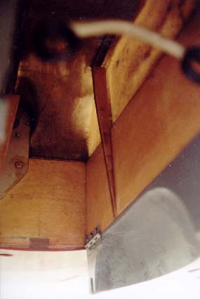
Last rnonth I checked the air in my tires and after I added some in all the tires and checked a few other things, I went flying. I popped the circuit breaker on retraction and for several days I continued to have that old problem. I put the aircraft up on jacks and manually cranked the gear up. It came to a stop two turns before it should have.
When I looked up in the nose wheel well, I could see very plainly the tire resting on top of the jack screw. The other doors were still short of closing.
I decided to correct the problem in as simple a way as I could, so I glued two tapered strips of spruce five inches forward of the back wall of the wheel well. The strip on the left side goes all the way to the top of the well and rests on top of the rear of the bolt bracket that is in the top of the well. The other tapered strip stops just short of the screw jack. Both strips taper to a thickness of one inch. The longer strip is approximately ten inches, the other is seven inches.
After gluing the strips in place, I painted a thick coat of epoxy on the rubbing surface of both strips, and then sanded smooth after it dried. Now if the nose wheel gets turned for any reason in either direction the side of the tire just kisses the strip and stops in an almost perfectly straight alignment in the top of the wheel well. It is not rocket science, but it works like a charm.
Joel Shankle
|
From "Construction Notes" Falco Builders Letter, March/June 2002 |
I have a minor problem with my landing gear. Upon retraction the right hand tyre touches rib 1 and my wheel well doors do not fully close because (the stick out about 2-3 mm). When the airplane was upside down everything was working well. Now I'm thinking about taking the 5.00x5 tires since they are somewhat smaller aren't they. Do they fit on my Rosenhan wheels?
Cipriano Kritzinger
I have a few comments. First, when the airplane is upside down, the springs on the ends of the screwjacks compress, and you can be tricked into thinking the landing gear will go 'up' that far, when it will not. When the airplane is in the normal, in-flight position, the screwjacks are in tension and the landing gear will be a few millimeters 'out' of the wing.
Are you absolutely sure that the shock absorber struts are fully extended? Some of our first struts were made with a plating method that caused the plating to build up on the piston at the largest point of diameter, and this could cause a minor interference with the recess in the aluminum. When the struts were fully inflated, the piston pushed its way in there and then it extended fully.
You can see the tire sizes on the wheel well door drawings. The wheels and tires are not interchangeable.
|
|
![]()