Notes & Comments
Maintenance
![]()
Notes & Comments
|
|
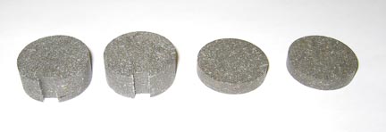
Owners of production Falcos sometimes contact us for parts. Here is a set of brake pads for the production Falcos. There are two pads, both 30mm diameter. One is 6mm thick, and the other is 12mm thick and with a 6mm wide by 3mm deep slot. These parts are no longer in manufacture, but they may be made from standard brake pad material with a lathe and milling machine. Ernesto Valtorta says that a friend, Elio Balbo, in Milan makes these for 40 Euros a set.
|
From "Construction Notes" Falco Builders Letter, March 2004 |
As he was preparing to get his Falco flying, Dan Dorr called to say that he and Brien Seeley weighed Dan's Falco on the CAFE Foundation's scales, which are accurate to a ridiculous degree. They concluded that the Flight Manual location for the CG location of pilot and passenger is way off, like eight inches. They concluded it was at 77" instead of the stated 85". Everything else came out right on the money. They said all you do is weigh the airplane empty and then with pilot and passenger sitting in the plane.
It was about this time that George Richards was weighing his Falco, and he reports "I concur with Dan with respect to the arm for the pilot and passenger. I made it nine inches further forward but Giovanni said he was probably about an inch further forward than he would have actually sat."
George began calculating the center of gravity with various loading conditions. I never want to advocate that anyone become casual or sloppy about weight and balance, but...
The forward CG limit is determined by the ability of the airplane to do a full stall in ground effect, and that really means landing. When you get your Falco in the air, you will quickly get a sense of how much elevator authority you have. You will probably worry a little bit about having possibly too-forward a CG, but then over time you will get a sense of how the plane flies, and you will stop worrying about it.
And on the aft CG, with a constant speed prop, you really have to load a bunch of stuff to get to the aft CG limit, and even then the airplane will tell you without you doing any calculation. When you get too far aft, the airplane will tip onto its tail. This happened with me once in the Corporate Disgrace, when I was in Idaho on my way to the CAFÉ 400 race. I landed, took John Harns for a ride, then filled up with fuel and perhaps a few more soft drinks in the cooler, and the plane was on its tail. I got in, had John lift and hold the stabilizer up while I started the engine. Once the engine was running, it would not tip back again. I didn't worry too much about it because I had just flown almost across the US with an essentially identical loading, so I took off. It was a little light on the stick, but certainly nothing dangerous or in the realm of positive instability.
And on gross weight, you'll find the Falco can carry anything you can get into it. You'll only run into problems at high altitude fields and with high temperatures. You're going to get very comfortable with the airplane very quickly, and you're going to start flying it like bush pilots fly Beavers, just throw everything in, start the engine and go.
|
From "Construction Notes" Falco Builders Letter, March 2004 |
Fred Doppelt reports that he talked to Larry Wohlers, who had paid a visit to look at the wreckage of his old Falco. As you may remember, the accident report cited a collapsed air intake hose. Larry reports that there was "no wire at all in the intake hose."
|
From "Construction Notes" Falco Builders Letter, September 2003 |
I was thinking about the accident of N33LW last night, and I thought I would mention to you that you may want to add to the check lists on the website for annual inspection "Inspect the intake filter and frame for cleanliness and integrity". There could be some more planes out there with frame problems. -- Glyn Russell
Thanks for the note. We've made the change to the check list that Cecil Rives did and also put a note at the bottom of "How to annual your Falco" by Steve Wilkinson. Also, because the accident was apparently caused by the collapse of the internal spring structure of the engine air intake tubing, we have included something about that.
|
From "Construction Notes" Falco Builders Letter, December 1996 |
Cecil Rives reports that, like Richard Clements, his ailerons were floating up about 1/2" at the trailing edge in flight. In checking things, Cecil found the aileron cable tension to be 25 lbs, far short of the specified 45 lbs. After tightening the cables to the correct tension, Cecil said the ailerons now come up about 1/4" at the trailing edge in flight.
|
From "Construction Notes" Falco Builders Letter, March 1995 |
Cecil Rives had a curious experience with his Falco. Quite suddenly his flaps refused to go down in flight, even though they still worked fine on the ground. He called to inquire if we had any ideas, and in discussing it, he mentioned that the problem had begun immediately after putting his plane through its annual inspection, and that in that process he had greased the lead-screw of the flap actuator.
First off, you don't need to grease this lead-screw except at enormous intervals-probably every ten years or so. It's a ball-screw device that has very little internal friction because steel balls roll between the grooves of the thread and annular rings inside the nut. It already has a certain amount of grease on it, and it will last a long, long time without any additional lubrication.
The flap actuator is a curious device, something known as an epicyclic ball-screw. How and why it works the way it does never ceases to amaze me, and I scratch my head as I describe to people how it works. Between the nut with its annular rings inside and the lead-screw, there is a sleeve-essentially a piece of steel tubing with holes that trap the balls. When the sleeve is allowed to turn freely, the path of least resistance for the balls causes the nut to move along the length of the screw. Stop the sleeve from turning, the balls will spin in place, and the nut will cease to actuate.
Another curious thing is that the greater the load on the screwjack, the greater the tendency to want to actuate. Conversely, if there is no load on the actuator, just the slightest amount of drag on the sleeve will cause the lead-screw to spin aimlessly in the nut.
Some years ago we had a problem with a batch of actuators that 'wouldn't actuate' and after some complaints we sent them back to our supplier. After much discussion, it was determined that the screwjacks had been over-greased, and that the grease between the nut and the sleeve was causing enough drag on the sleeve that it wouldn't actuate. They simply wiped all the excess grease off.
We concluded that this same phenomenon had probably struck Cecil's Falco, however after wiping off the excess grease, the problem persisted. Cecil finally went digging into the bowels of his airplane to see what he could find. He found that on the back face of the actuator motor, there are six flathead screws which hold the gearbox together. These seat into some dimpled star-type lock washers, and this causes the screws to stand proud of the surface of the gearbox. Two of these screws were hitting the actuator supports. Cecil ground away some of the metal on the actuator supports, and the problem disappeared.
Weird as it sounds, I think all of this makes some sense. I think the problem was caused by a combination of excessive grease and the problem of the screws hitting the bracket. With the flaps fully extended the screws would cause a side-force on the nut causing a sideways binding action on the sleeve. In addition, any upward pressure on the flaps would contribute to this action by pressing sideways on the nut. It sounds mystical, I know, but I think that's what happened.
|
From "Construction Notes" Falco Builders Letter, December 1994 |
There is some question about whether homebuilts require annual inspections, and the subject came up recently in a letter to Kitplanes from an experienced hired-gun builder who said that homebuilts do not require annuals. He said the regulations are quite clear. Editor Dave Martin agreed that the letter-writer was correct, and that the only thing required is something called an "on-condition inspection." But since all Falco builders are compulsives anyway, it's likely that most of you are doing the same thing anyway.
|
From "Construction Notes" Falco Builders Letter, December 1990 |
Owners of production Falcos take note: The brakes on my Falco gave out some time ago and when we put it through the last annual inspection, I asked the mechanics to fix the problem. At first, I thought the problem was with a leak in the system, but it turned out that the rubber seals in the master cylinder had become completely destroyed, apparently by solvents.
The Series III Falcos used an automotive master cylinder for the brakes, and this aluminum forging is located under the cockpit floor. The seals were rectangular in cross-section, and we had no idea where to get any. Rather than fight with that problem, I decided to redesign the thing for standard O-rings.
This turned out to be a relatively simple matter. The aluminum cylinder has a 1.00"ID. I took the brass piston and redesigned it for standard 1/8" by 1.00"OD O-rings and designed the grooves to the depths specified in the standard O-ring design guides. Our machine shop had the thing made in an hour, and then I found that we needed to spend another hour adjusting things.
The original design is an astonishingly simple design with no valve in it. The piston has two O-rings, and when the piston is completely 'retracted', the position of the O-ring is such that it just barely passes the port from the brake reservoir, so fluid leaks in to replenish the system. Once you press on the pedal, a rod shoves the piston past the port and the system is sealed. I found that in my first attempt at reverse-engineering this part, the O-ring did not pass the port at all. This was easily solved by sanding on the end of the brass piston until the port opened.
The second problem was that the O-rings introduced more friction into the system than the return spring could accommodate. You could push the cylinder down all right, but the spring would not push it back. Back to the machine shop I went, and the machinist put the piston back on the lathe and took a few thousandths out of the bottom of the O-ring grooves until the piston would move freely enough for the spring to work.
Now I have a system that doesn't depend on weird, God-knows-where-you-get-them seals, and the really good news is that the brakes on the airplane are suddenly very powerful. I had always thought that the weak brakes on my old Falco were something to do with the brakes themselves, but I can now push on the pedal, and the airplane actually stops right-now. This is something of a luxury considering that I had been flying it for a full year with literally no brakes at all.
|
From "Tool Talk" Falco Builders Letter, June 1987 |
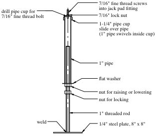
My wing rests on two Sears jackposts and a one-by-two leg clamped to the rear of bulkhead #6. Each jackpost is welded to a foot-square steel-plate base and has a large threaded pin at the top modified as shown on the drawing. I had mine welded perpendicular to the footing plates and I shim the footings slightly so the jackposts sit at an angle to match the dihedral of the wing, but you could also take the trouble to cut the bases of the jackposts at an angle and weld them to their footings so they sit slightly cocked and thus enter the jackpad squarely.
They aren't something you'd want to go into the A&P business with, jacking half a dozen airplanes a day, but for the number of times I'm going to be jacking the Falco up and down, the price is right: $30.98 for a pair of short Sears jackposts, $9 for shipping and $15 for the necessary welding. The jackposts come in a variety of lengths, from one foot on up to eight. The ones you want are the next-to-the-shortest, and the range of heights attainable is 20" to 36", with infinite variations in between attainable by turning the threaded rod and/or sliding and resetting the inner bore of the jackpost. They are Sears #64 F 99793C, $18.49 apiece or $15.49 each for two or more, and they will support 16,000 pounds each. Should be enough for a fully fueled Falco.
I know you said Dave Aronson knocked his airplane off his jacks, and I'm sure you could do that with this rig as well, but that's why they put signs all over airplanes that are sitting on jacks: you can knock a Bonanza off a thousand-dollar set of hydraulic jacks, too, if you jump up and down on the wing walk enough times.
Steve Wilkinson
What happened to Dave Aronson was that his home-made jacks failed and collapsed. When I was in his shop, the Falco was on a very sturdy jack under each wing and the tail was pinned in place to a pipe in a cut-down barrel filled with concrete. It was remarkably solid-Dave Aronson and John Holm would leap on to the wing walk from a run.
The top of the Sears jackpost comes with a flat top, which Steve filed to a conical contour and then welded a small pin/extension to the top center. He cut a couple of rubber pads from an inner tube to protect the treads of the jack pad fitting. The little finger on the top of the jack could damage the threads in the aluminum jack pad fitting. When you tie the airplane down, you use the eyebolts supplied, but when you jack the airplane, you should use a bolt in the fitting.
There are two schemes, depending on whether the top of your jack is a "male" or "female". In either case, start with a 7/16-20 x 1-1/4" hex head bolt (with threads all the way to the head) and a large hardware-store washer. Many people braze the washer in place. If the top of the jack has a depression, then you can just grind the head of the bolt to a nice spherical radius to fit. In some cases, I've seen where builders have enlarged the head with gobs of braze and then ground it to a spherical radius.
If your jack has a pin on the top, then you have to modify the head of the bolt so it is a matching cup. Again, you can enlarge the head with braze and then grind out a depression. I'm not sure if most FBO's jacks are boys or girls, but it is a good idea to make up some jacking bolts and keep them in the airplane in case you get caught far from home and need to jack the airplane.
Alfred Scott
|
From "Construction Notes" Falco Builders Letter, June 1986 |
John Harns mentioned that when he did the annual inspection on his Falco, he found a very small, hairline crack in the weld for the flange on the nose gear axle. It wasn't serious or dangerous, but it is something for other Falco owners to look for on inspections.
|
From "Construction Notes" Falco Builders Letter, June 1986 |
In discussing his plugged injector nozzle, John mentioned that the little tube from the spider had a very fine wire in it and didn't understand what it was for. I had never heard of such a thing, but I called Neil Hall, my favorite aircraft mechanic, who said that the wire is not supposed to be in there and is probably the reason the injector was plugged. Neil also pointed out that the size and length of the tubes is important. Lycoming cuts all of the tubes to the same length so that they will have the same friction and thus an even distribution of fuel to each cylinder-the wire will certainly not help. A recent Lycoming service letter warns against using primer lines for the injector. They are the same O.D. but different I.D., and the service letter tells you how to check this.
|
From "Tool Talk" Falco Builders Letter, December 1986 |
Maintenance snippets from Light Plane Maintenance. First choice for cleaning plexiglass is Pledge with Job Squad paper towels. Pledge also works to remove bugs from the propeller and wing leading edges, although you should sometimes precede the Pledge with Fantastik and water.
O-Ring replacements for the parking brake valve.
On cam: MS28775-010 (3 O-rings)
On poppets: 2-006-N507-90 (2 O-rings, this is a Parker part number)
On outlet fittings: MS28775-012 (2 O-rings)
|
From "Construction Notes" Falco Builders Letter, June 2001 |
I was doing an annual and unfortunately, my plane fell off the jacks. Fortunately, I was not under it, or I would be in the funeral home today. Here's my question. I now have a 4" x 4" hole in the lower right wing skin just aft of the main wing spar and between two ribs. About rib 4 and 5, I think. The other wing has a 2" x 2" crack in the skin in the lower leading edge, about half way of the wing. There does not appear to be any damage to any structural member, either spar or ribs.
Can you tell me the most appropriate way to repair the skin? Do I need to remove skin out to a structural member such as the spar and ribs and replace it with a scarfed skin?
Glyn Russell
Oops. Sorry to hear about this. The same thing happened to Dave Aronson years ago. Repair is relatively easy. Cut out the broken plywood, and then put in a patch. While you will probably scarf the plywood, I suggest putting in a strip all around the hole on the inside so you have something to push the plywood into. You can also use sheet metal screws as 'clamps' while the glue is drying.
|
From "Construction Notes" Falco Builders Letter, September 2001 |
A Falco owner just completed an annual on a Falco he bought, and he says the right wing is heavy. Would it help to adjust the turnbuckles on the controls to lower one aileron and raise the other one? The answer is that adjusting the turnbuckles simply moves the control stick relative to the ailerons, and it will accomplish nothing as the ailerons will seek their own level.
|
From "Construction Notes" Falco Builders Letter, September 2001 |
Art Domingues has been burning up the skies with Quentin Rench's Falco, using it as a regular corporate transport on his sales rounds. He flies the Falco often at night, and has been replacing the landing light every ten hours or so. Recently, he has replaced the standard bulb with a Lopresti Boom Beam (www.FlyFast.com) with costs about $900.00, but the bulb has no filament and this is supposed to last 'forever'. Sounds like a lot of money, but don't ask Art how much he has spent on light bulb replacement!
|
From "Construction Notes" Falco Builders Letter, December 2001 |
Larry Weldon't low-cost aircraft jack.
|
From "Construction Notes" Falco Builders Letter, December 2001 |
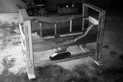
Since I finished my Falco I have always had the devil of a time removing and installing the lower half of the cowling. With no one around to help it bordered on the impossible.
The contraption I built and that is shown in the photos really makes a simple job of it. I made it almost entirely of 1 x 4 western red cedar. The only exception is the cradle frames that contact the cowling. These are made of 1 x 8's cleated together and then cut out to fit the profile of the cowling. The cut-out edges are lined with 1/2" felt strips to protect the paint finish. The red cedar material is widely used in fence construction and is readily available at lumber yards or fence companies.
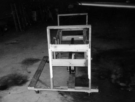
The cradle moves up and down guided by cabinet drawer slides. The up and down travel is about 12 inches. (The slots you can see in the photos may be disregarded as they were originally made with the thought that the cradle could be guided by some long pins sliding in them. This didn't work as the cradle would bind in them.)
The hydraulic scissors jack is obviously over-kill. It's just that it had been sitting around in my garage for years without being used for anything. I would imagine that a simple lever arrangement would work as well.
The entire carriage moves around on four swiveling wheels.
Cecil Rives
|
From "Construction Notes" Falco Builders Letter, September 2002 |
I hope that you can find time to answer a question, even though it concerns a Laverda Falco. The forward aileron control cables on my Falco is routed on top of of diagonal members of the forward ribs from Sta. 2 outside the rib supporting the landing gear, until Sta. 2 before it attaches to the bellcrank. (The straight line from the hole in the solid rib at the gear, to the bellcrank runs below all the rib diagonals.) Is this a normal 'derouting' to avoid excessive tension in aileron cables, when the wing flexes?
Hardy Vad
The Series I, II and IV Falcos all use the same aileron control cable design that we use with our kits. The cables connect the control stick to the aileron bellcrank as a direct connection, and there are two pulleys located on the wing rib at Sta. 2 to accommodate for the change in the direction of the cables required by the dihedral of the wing. The cables should go in a straight line from the control stick to the cable, and then in a straight line from the cable to the aileron bellcrank.
If I understand you correctly, the cables do not do this, instead they go 'up and over' a part of one of the wing ribs. This is a mistake and the cables should be re-routed for a straight-line connection.
The Series III Falcos had a different design, with a pushrod from the control stick to a bellcrank at wing rib No. 2. I have no idea why.
|
From "Construction Notes" Falco Builders Letter, September 2002 |
Cecil's Fuel Line. Recently I removed the fuel injector nozzles from my engine (IO-360-B1E) for cleaning as part of my annual inspection. After installing them back in the engine I performed a leak-test by turning on the electric fuel pump. The injectors showed no sign of leakage but to my surprise I noticed a small spray of fuel being vented from the fuel pressure line that connects the fuel distributor or "spider" to the bulkhead fitting at the rear left side of the engine baffle. The fuel was being deposited directly on the #4 cylinder head! The leak was coming from the fitting at the end of the 1/8" o.d. aluminum line where it connects to the bulkhead fitting.
Thinking that the fitting had loosened for some reason, I applied a wrench to the fitting to tighten it. As I did the line popped completely out of the fitting and lots of fuel sprayed out! I turned the fuel pump off and removed the fitting. It seems that the line had parted inside the fitting and was probably caused by vibration even though the line was supported midway by clamps just like the fuel lines to the fuel injector nozzles are supported.
My solution to the problem was to replace the aluminum line with a flex line. The flex line is also encased in a fire sleeve. The line measures 12 3/8" from the end of one fitting to the end of the other fitting. This arrangement seems to me to be a much safer and reliable connection. I mentioned the incident to Bill Russell who decided to inspect the line on his Falco. He also found a crack although the line has not completely parted. He has replaced his with a flex line as well.
I have about 430 hours on my Falco and Bill has a little over 100. It would appear that an inspection of this line would be a prudent thing to do. Let Sequoia know if any more cracks are found.
Cecil Rives
|
From "Construction Notes" Falco Builders Letter, March 2003 |
I learned today that an AD was issued in 1997 regarding the fuel pressure line that comes from the spider to the back baffle, which Cecil and I replaced with a flex hose. It is an AD issued by Lycoming and I believe the # is 93-02-05. I don't know if it is applicable to Experimental aircraft, but I think the guys out there should really give this change a thought!
Bill Russell
|
From "Construction Notes" Falco Builders Letter, September 2002 |
Magneto Harness Woes. I have just replaced the Slick magnetos on 63KC as the old ones were close to their projected life. I purchased (from Aircraft Spruce) a Slick kit (K-4567) which is the one designated for the IO-360-B1E engine. The kit includes the magnetos (#4370 and #4373), new wiring harnesses and eight Autolite spark plugs (UREM38). For those of you contemplating a similar purchase be forewarned! The wiring harnesses are way too long! For instance, the wire to the top plug on the #1 cylinder is two feet longer than the one on the old harness that I am replacing. All the other wires are proportionately longer as well. These new harnesses are labeled M-2983 (l.h.) and M-2984 (r.h.) and come in a box labeled M-4006.
If you don't want to have coils of ignition wire hanging all over your engine compartment you need to obtain an M-1795 (l.h.) and an M-2992 (r.h.). They come in a box designated M-4001. These harnesses are what I have had on 63KC since I completed it, and they are a perfect fit.
When I discovered the long harnesses in the Slick kit, I tried to get Aircraft Spruce to exchange them. After a week of pleading with them I was finally told to contact Unison (Slick) for the exchange. Unison cheerfully agreed to the exchange and within a few days I had the correct harnesses in my hands.
I suppose one might be better off buying the mags, harnesses and plugs as separate items rather that purchase the kit even though it's probably more expensive. Regardless, don't give up; there are shorter harnesses available.
Cecil Rives
|
From "Construction Notes" Falco Builders Letter, March 2003 |
Trim Tab Control Wheel Play. I have been bothered by the amount of "slop" or play in my trim tab control wheel. It seemed to be about 1/8 of a revolution in either direction before there was positive movement of the trim tab itself. I determined that the problem was in the right angle gear box to which the control wheel is attached. There appeared to be considerable play inside the box itself and by applying tension on the screwjack I discovered that the play could be almost entirely eliminated.
The screwjack can be removed from its shaft by driving out the roll pin that secures it to the shaft of the gear box. With it removed I placed three AN960-416L washers on the shaft and reinstalled the screwjack. This eliminated almost all of the play. The operation of the control wheel now is much more positive. Your gear box may require more or less than three washers so you may have to experiment as to what works best in your case. The roll pin is not too difficult to remove, however if you try to do it with the gear box in place the shaft/screwjack should be supported in some manner.
Cecil Rives
|
From "Construction Notes" Falco Builders Letter, March 2003 |
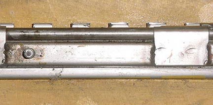
|
As promised I have attached some pictures of
the keeper on the pilot's side. |
I had to abort two successive takeoffs today as a result of the pilot's seat sliding back rapidly as the aircraft accelerated from a standstill, leaving me unable to reach the rudder pedals and brakes. I just managed to regain some control before the aircraft left the runway by immediately closing the throttle and then rapidly releasing the seatbelts in order to be able to slide down the seat to apply the brakes.
I considered at the time the reason for the seat giving way was because I had not ensured the seat adjustment was properly seated in the keeper. I taxied back to the hold for another departure and had plenty of time to check and recheck that the seat was secure by pushing back really hard with my rear end against the back of the seat. Reassured that everything felt fine, I lined up for departure, applied full throttle, as the aircraft accelerated the thrust pushed my body back hard against the back of the seat and once again the seat shot back leaving me unable to reach the pedals. This time, however, I was ready and very quickly slowed the aircraft down, abandoned the departure and made my way very sheepishly back to the hangar.
Once back at the hangar I removed the seat and discovered that the keeper was badly worn at the point most frequently used. Why I have related this in detail is that the second time I did check carefully that the seat was fixed in position securely. It seems that simply pressing one's butt against the bottom of the seat is not sufficient, you need to push and lean back in the same way our body is forced to when full throttle is applied. In the future, I shall be doing that and also I will be checking at the annual inspection for wear on the keeper.
Stuart Gane
Stuart's first inclination was to replace the keepers, but I suggested just filing them square again, and that is what he has done. Stuart said that it was his practice to slide the seat back every time he got out of the plane, and this is clearly why it has worn so badly. From now on, Stuart is going to abandon that practice.
|
|
![]()