Ailerons & Flaps
![]()
Ailerons & Flaps |
|
|
From "Construction Notes" Falco Builders Letter, March 2004 |
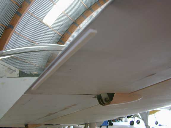
Giovanni Nustrini came up with a variation on Wayne Milburn's trim idea. It is just a closed cell, self-adhesive foam strip. George reports it's "very light and simple and works great."
|
From "Construction Notes" Falco Builders Letter, December 1985 The discussions listed below are all obsolete now, as far as I'm concerned, because these were written before the Falco construction manual chapters that have revolutionized the building of the ailerons and flaps. But I'm going to leave these notes here for a while in case there's something to be gained from reading them. Alfred Scott |
Using our construction manual, Terry Smith built the ailerons and flaps as a single unit. He said the construction went along nicely, and he had no trouble getting everything together. Along the way, he made a mistake, and Terry asks me to pass on word of his boo-boo so that others won't repeat it.
When Terry glued the trailing edge ribs to the spar, he assumed that they were cut to the right angle. Without a jig, there was no way of checking these. As luck had it, one side came out nicely, but the other didn't. Terry just sawed the ailerons and flaps off aft of the spar and re-built the things with little trouble. This time he used a jig to hold things in position when he skinned it, and Terry offers that jigless construction of the aileron and flaps is not the way to go.
That said, the next thing I have for you is a letter from Falco builder Jonas Dovydenas on his jigless way of building the ailerons and flaps! So, take it away, Jonas.
Jonas and the Aileron
Dear Alfred,
Let me tell you about my jigless way to build the aileron-flap
structure. The wing is vertical across two saw horses, leading
edge down, and level in both planes. The spar is prepared in the
usual way. Drill the holes, draw the lines, glue on the pads and
fillets, etc.
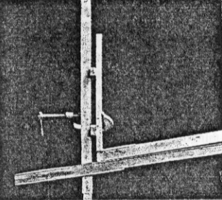
The ribs are cut on a radial arm saw to the proper angle so they stand vertically without support. Put the spar on the wing and raise the inside end 155mm, the amount of hinge axis displacement.
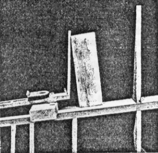
Clamp the outside rib to station 14 rib with a 10mm spacer. Secure the inside rib with push pins and a wooden block. I use T-88 so the clamping pressure and joint thickness are not critical, a weighted spring looped over the rib is sufficient.
Fabricate the hinge shims and clamp the hinges in place. Check for free action, alignment, etc.
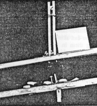
String a fishline between the tips of the wing ribs. String two lines on the sides, about 25mm from the spar. Line up the ribs, top and bottom. Note the spacer for the double rib. Use pushpins to keep the ribs from sliding downhill, a block of wood to keep them from falling over the other way. I pushed the ribs down into a thick glueline-they stayed put without weight on them.
The rib tips are cut at the 8mm thickness line, the trailing edge is clamped all the way across, the lines traced for the notches.
The fish line is raised slightly above the tips, glue applied to the notches, the length of the trailing edge is aligned with the string; if weight is needed to secure the alignment, I clamped a weight to the place where the line wandered off.
The virtue of this method for me is that most of the measuring is done along sight lines and verticality is easily checked with a bob or a sighting along the wing ribs. Also, to me, this is a common sense way of working, one thing leads to another. The geometry of the wing is always there in front of you.
I dislike making abstract measurements, numbers taken from a table or a plan. The origins and purpose of the measurements are in sight, errors can be more easily spotted-when something doesn't look right, it probably isn't. For example, the ribs are free standing on the spar, they can be moved in and out of alignment, you see the thing in perspective and realize that referring to a + or .5mm measurement (as you like to point out when waxing eloquent about the plans) is neither necessary nor helpful toward maintaining project sanity.
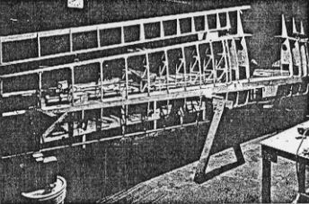
I suppose some people like to be programmed like a computer-tiny tedious steps at a time-but I can't stand it. Furthermore, as you know, I will go to great lengths to avoid jigs (though I do like the Scottish), at least until the big contract for three planes a month comes in from the Bolivian Air Force... oops, proprietary info., delete that last line...
Yours in affectionate madness
Jonas Dovydenas
|
Okay, I don't have any trouble with the method that Jonas describes here. My hang-up comes when you install the leading edge ribs, leading edge strip, then sand the ailerons and flaps for the skin and then skin them. I cannot see how you can skin these things without holding them in a jig. A few Falco builders have skinned the ailerons and flaps "on the wing" but to my knowledge, all ended up with twisted control surfaces. The method that we will be describing in the construction manual is similar to the one used by Jim DeAngleo, John Oliver and some other Falco builders. What you do is build the ailerons on a flat bench. The spar is on the edge of the table and the trailing edge ribs are positioned with a long tapered wedge at the 95% chord station. Working from the new drawings, the dimensions are easy to come by. Steve Wilkinson has used the method and reports as follows: |
I haven't tackled the problem of skinning a flap/aileron unit yet, but I did want to let you know that your single-long-wedge method of jigging the flap and aileron ribs for washout seems to work just fine. I actually used an inch-square piece of clear pine 10 feet long and made two-inch wide notches in it centered on every rib station, then carefully filed and sanded those notches to the precise depth for the necessary "lift" at each station at 95 percent of chord, figuring that would be easier and more precise than ripsawing an extremely narrow 10-foot-long wedge.
One disadvantage of my method, however, is that the piece becomes quite delicate by the time you weaken it with a series of the deepest notches. Another is that the inch-high areas that stand up between the notches now need to be removed in order to use the jig during skinning. I think if I had to do it again, I'd ripsaw a wedge to roughly the right shape along its entire length and then do fine-tuning by hand, with file and sanding block, at each specific rib location.
Another thing I'd do is try to use a piece of wood considerably less than an inch thick, since an inch of thickness, when its forward edge is aligned with the 95-percent-of-chord locations along the ribs, means the rear edge gets in the way of affixing the trailing edge strip at the more outboard of the stations.
Naturally, the jigging process however done presupposes an absolutely flat and level jigging table, with the spar clamped to its edge and if necessary shimmed slightly for absolute verticality.
Steve Wilkinson
Gordon Cook wrote me that his ailerons and flaps were the most difficult part of building the Falco. He said that the left side took him two months and the right side took one week. Now, that's a good learning curve! I wrote Gordon to see what notes he could pass on.
Gordon assembled his wing with the trailing edge up. Before assembly, he drilled all holes possible in the main wing spar, then he marked the chord lines and the rib location on the spar. He used a tight line to insure that there was no sag in the spar.
Before gluing on the aft ribs, he sanded an angle on the ribs to accept the aft spar. To properly locate the aft end of the wing ribs, he constructed two templates of the outline of rib No. 1 and No. 14. With these clamped in place, he ran a tight line for the intersection of the chord line and the forward face of the aft wing spar. This line was used to align the chord lines on the ribs. He glued ribs 3, 9 and 13 in place first and then used these to support the others while the glue dried. This was done by placing a 3x15mm strip across the ribs. Gordon held it in place with lead gluing weights (about 1"x1"x3") over each ribs.
After all aft wing ribs were glued, the aft wing spar was glued in place. Gordon drilled no holes in the aft wing spar at the time. He did drill the flap/aileron spar for the hinges, using a 13/64"Ø drill instead of a 3/16"Ø drill for the bolts. These holes were oversized on purpose to allow Gordon to get everything lined up and later Gordon filled the holes with epoxy.
The flap/aileron spar was blocked and clamped in place. To align the flap/aileron spar, Gordon lined it up with the templates at Sta. 1 and 14, extending the bottom forward face of the spar to the outline of the rib. Like Jonas Dovydenas, he used a tight line to align the ribs just aft of the flap/aileron spar. He also used a tight line along the trailing edge. The ribs were aligned with the tight lines, and they were held in place with wood blocks cut to the required rib-to-spar angle.
Gordon assembled and loosely bolted the hinges to the flap/aileron spar, and he clamped the hinges to the aft wing spar, using tapered wedges to properly align them. When the hinge bolts could be easily removed by hand in all flap and aileron positions, Gordon found that the alignment was right. He started the holes by drilling with a 3/16"Ø drill. After all holes were just started, he finished the holes off with a 13/64'Ø drill in an alignment block. This was a 1-3/4" piece of oak which he had drilled on a drill press. With the point of the 13/64"Ø drill in the started hole, he clamped the alignment block securely and completed the hole.
To install the bolts, Gordon coated the hinges, bolts and channel-nuts with mold release. He bedded hinges, channel-nuts in epoxy and coated the bolts with epoxy. This filled out the oversized holes.
It seems that Gordon's primary hurdle cleared is the proper alignment of the hinges. I still think the aileron and flap hinges should be installed before the aft wing spar is installed in the airplane. This will be easier to do once you have our new drawings in which you will be dealing with dimensions that are more convenient for your purposes. Steve Wilkinson expressed a high frustration factor with getting the aileron and flap hinges all lined up with each other until he tried Jim DeAngelo's trick with a long 1/4"Ø steel rod. All you do is set all of the 1/4" hinge bolts to one side and put the long rod in their place. This way, the hinges all align themselves. Then all you have to do is to clamp and drill for the hinges. Actually, Steve says he cheated and used a couple of three-foot-long wood dowels which he spliced together.
|
|