 Centroid Tool Centroid Tool
The Centroid tool calculates the centroid and optionally the moment of inertia of objects that you click on with the tool. These objects may be rectangles, ellipses, circles, polygons, b-splines, splines, Bézier and groups containing these objects. Other types of objects (lines, text, arcs, etc) may be in the group but they are ignored. All objects must be closed shapes for the calculations to work properly, and the Centroid tool closes all open shapes prior to making a calculation.
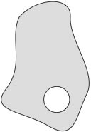
Void objects are holes.
A group of objects may consist of 'solid' and 'void' objects. 'Solid' objects will be totalled in the calculation. 'Void' objects will be subtracted from the calculation and are intended as hollow shapes or holes in a cross-sectional shape.
The Centroid tool will calculate which objects are within other objects. Objects within 'void' objects are considered as solid objects. When objects overlap, the Centroid tool will show the results with the text in red, and with a warning that objects overlap. You can also confuse the Centroid tool by creating duplicate objects.
Multiple objects must be in a group to be considered as a single object.
A polygon which crosses over itself ('complex polygon') will result in completely inaccurate results.
The Centroid Tool calculates and reports the moment of inertia and other values about the X axis and optionally about the Y axis.
(Remember, moments of inertia are calculated about an axis -- not along an axis. For example, Ix indicates the moment of inertia about the X axis. This means that Ix is influenced by the parts of the area above and below the X axis, ie values in the Y-direction, and conversely Iy is influenced by the parts of the area to the left and right of the Y axis, ie in the X direction.)
The Centroid Tool also draws lines on the Principal Axis of the object for identification when any calculation of the moments of inertia are made. This makes it easy to rotate the object to align the Principal Axis to the X axis and then, after running the Centroid Tool again, you can obtain full report of values for the Principal Axis.
The Centroid tool uses the Area Units and Area Accuracy of the Drawing Setup/Units pane, except that acres and miles are reported at feet, and hectares and kilometers are reported as meters. Thus the units may be mm, cm, m, inches and feet.
The Centroid tool converts rounded rectangles, Béziers and B-splines to polygons to make all of the calculations for area and moments of inertia. The conversions of some shapes vary in extremely small amounts depending on the size of the object, so it's possible you may see some very small variations for the same shape comprised of Béziers and B-splines at different sizes and scales. The moments and areas of circles and ellipses are found by direct calculations.
In an effort to provide very precise areas, the Centroid tool bases its conversion of objects to polygon on the Area Accuracy of the Drawing Setup/Units pane up to six decimal places. It will be accurate up to six decimal places for square inches at 1:1 scale, which produces an area accurate to a millionth of a square inch. Setting the Area Accuracy to higher numbers will change the display, but the accuracy is never calculated higher than six decimal places for square inches.
Terminology:
Section Area A: The net cross-sectional area, after subtracting the interior holes ('void' objects). Expressed in units^2.
Neutral Axis: The Centroid tool uses the X and Y axes through the Centroid or through the Ruler Origin. If you are only considering the beam by itself, then you would only be interested in the calculations made about the Centroidal axes.
The Ruler Origin would typically be used when you want to add and subtract values for built-up sections, because you cannot add individual values that have been calculated about individual centroidal axes. This is because each section has a geometry relative to the other sections and the 'square of the distance' rule comes into play, ie the farther the sections are away from each other, the highter the resulting moment values will be.
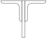
The second reason for calculating moment values about non-centroidal axes is because in some structures, an individual beam can be forced to bend around some other axis. An example is a truss. In this case, we have two sections, being the top and bottom chords, held apart by some form of bracing. This has the effect of forcing the chords to bend around an axis somewhere between the two chords. To calculate the stress in one of the chords, an engineer needs to know the moment values for the section when it is calculated around this other axis.
Moments of Inertia Ix, Iy, Ixy: The second moment of the area with respect to the selected axis, a measure of the stiffness of the cross section and its ability to resist bending moments. Ix is about the X axis; Iy is about the Y axis. Ixy is called the product of inertia, and it basically describes the symmetry of the object. If an object is spinning about its centroid and the object has an Ixy = 0, it will be in balance and there will be no wobble or vibration. If Ixy equally 0, it will be reported as 0.0, otherwise it will be reported to the decimals specified. Expressed in units^4.
Mininum/Maximum Monents Imin, Imax: Minimum and maximum values for Ix and Iy. Imin, Imax and the Principal Axis are crucial parameters used to analyze the performance of a beam in compression. The principal axis is the neutral axis about which the moment of inertia I is a maximum for the object. Imax is the moment of inertia about the principal axis, and Imin is the moment of inertia about the axis that is perpendicular to the principal axis. If the principal axis lines up with either the x or y axis, then the Imin and Imax will equal Ix and Iy, although they may be reversed. Expressed in units^4.
Polar Moment of Inertia Ip: The moment of inertia with respect to the z axis (normal to the section plane). Expressed in units^4.
Extreme Fiber X, Extreme Fiber Y: The point in the cross-sectional shape farthest from the neutral axis. This is used to calculate the section modulus, and only applies if the neutral axis is about the object's centroid. Extreme Fiber X is the horizontal distance from the Y axis. Extreme Fiber Y is the vertical distance from the X axis.
Section Modulus Sx, Sy: The section modulus is useful for calculating the extreme bending stress, and only applies if the neutral axis is about the object's centroid. Sx is about the X axis; Sy is about the Y axis. Expressed in units^3.
Radius of Gyration Rx, Ry: The distance from the selected axis to a point at which the entire area may be concentrated and still have the same moment of area as the distributed area. It is used as a measure of the stability of a column. Rx is about the X axis; Ry is about the Y axis. Expressed in units of length.
Principal Axis: The neutral axis through the centroid that produces the maximum moment of inertia, Imax. In other words, the Principal Axis is the axis about which a beam is the 'stiffest'. The Centroid tool indicates the Principal Axis with a centerline with an arrow on one end. The axis perpendicular to the Principal Axis is shown with a centerline with no arrows. |
To set the behavior of the tool:
Press the Option key and select the Centroid tool from the Nuts & Bolts palette. The following dialog will appear:
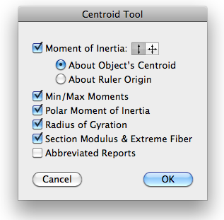
You may select to calculate the moment of inertia, which will also calculate a number of additional things.
Select if you want the moment of inertia calculated about the X axis, or about both the X and Y axes.
You may select to have the moment of inertia to be calculate about the object's centroid or about the ruler origin.
Select Min/Max, Polar Moment of Intertia, Radius of Gyration and Section Modulus & Extreme Fiber if you want these to be reported.
To use the Centroid tool:
Select the Centroid tool from the Nuts & Bolts palette.
Click on the desired object.
The Centroid tool will place a centroid marker at the centroid of the selected objects. If you have selected the Moment of Inertia option, lines will be drawn to show the principal axis angle of the shape and a text will be placed in the drawing with a report on the characteristics of the shape.
If the Centroid tool encounters any open shapes, it will close them, and this will be reported in the text report and the report will be in red, since it may result in an inaccurate report.
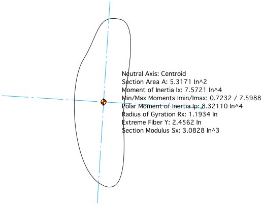
Blue centerlines show the principal axis angle.
In this case, the moment of inertia is calculated about the object's centroid.
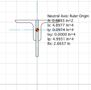
In this case, the moment of inertia is calculated about the drawing ruler origin.
This is useful for calculations of a truss. The report is abbreviated.
Many thanks to Derek Dubout for his assistance in creating the Centroid Tool. |
|