|
|
The WildTools 3D palette contains a number of tools which greatly simplify the process of drawing three-dimensional depictions in the 2D world of a PowerCADD drawing. These are axonometric drawings, commonly called '3D' drawings, and they come in three types: isometric, dimetric and trimetric, which differ only in the angles used for the drawing axes.
While you could always do isometric drawings in PowerCADD, prior to WildTools 3D you had to be familiar with the mechanics of isometric drawings, and you had to constantly remind yourself of the correct angles to use. And there were many common drafting problems that were extremely difficult. As you will see, WildTools 3D makes child's play of some of the most difficult problems in technical illustration and axonometric drawings. There are two ways to create a 3D drawing using WildTools 3D: from scratch, or by shearing. Creating a 3D Drawing from Scratch Much of the extraordinary power of WildTools 3D comes from the way dimensions are handled in the Edit Window. Lengths, angles and offsets are relative to the current drawing plane. If you've spent any time with axonometric drawings, you know the difficulty of locating a point in space. If you want to locate a new point in the drawing at a location relative to another (say 35mm at 15°) then you had to draw two construction lines. However, with WildTools 3D, you just draw a line, and tab into the Edit Window as you would with orthogonal drawing. Nothing to it! Creating a 3D Drawing by Shearing WildTools 3D vs 'Real 3D' Before you get snippy about this, it's a good idea to remind yourself that just because you have a 3D drawing, you don't necessarily have anything that is very useful. These programs are confusing, notoriously difficult to use, and they add a lot of extra complications to the task of drawing. While there are some good 3D programs, 3D has largely been the fool's gold of the CAD world. Naïve users often imagine that they must have 3D to have a complete program, and then they discover that the capabilities are difficult, confusing and take far more time than they are worth. Simply put, the vast majority of users of 2D/3D programs make very little use of the 3D capabilities. So we ask that you judge WildTools 3D not by what it is, but by what it can do for you. If you are an experienced WildTools user, chances are you can begin to draw three-dimensional depictions in a few minutes. However, don't let the ease-of-use fool you-WildTools 3D is by far the most powerful set of technical illustration tools ever offered on any computer. Tool Duplication To set the 3D axis angles for
WildTools 3D:
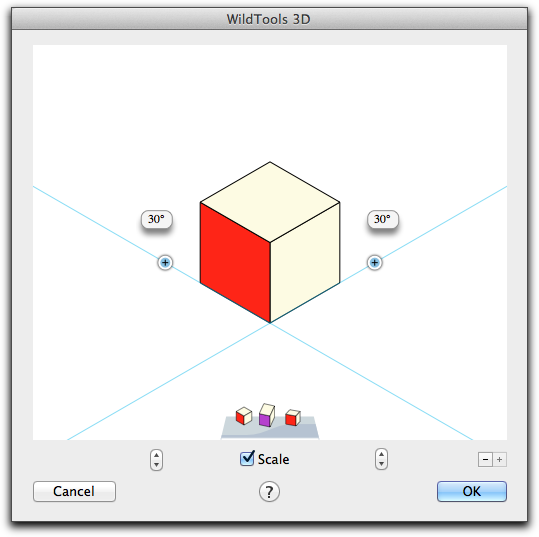
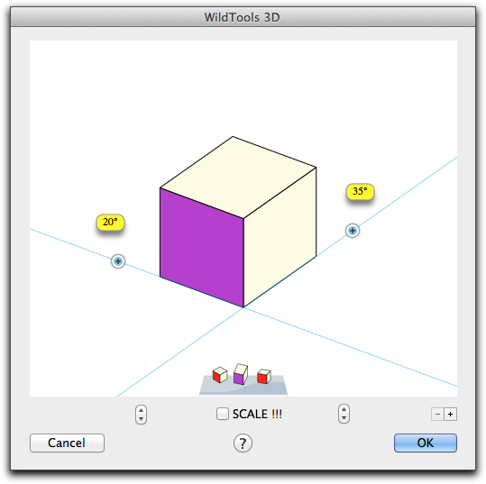
Press the click on the triangle in the bottom right of the 3D Cube window. The following dialog box will appear:
Scale turns on Axonometric Scaling Click the up/down steppers to adjust the X (left) and Z (right) axis angles. Click and drag the angles on each side of the cube. The 3D axis angles determine:
The Scale option which provides axonometric scaling -- the foreshortening of receding lines. This produces a projection of the drawing onto a picture plane, similar to a perspective drawing, however parallel lines remain parallel. Thus, the projection may be thought of as a perspective drawing viewed from infinity. To produce an axonometric projection, the axes are scaled. In the case of a '30-30 isometric' projection, the scaling is the same for all three axes. In a trimetric drawing, each scale is different. Because of the calculations required, axonometric scaling is seldom used in commercial practice.
Isometric drawing are popular because they are easy to draw and dimension, but equal importance is given to each of the three visible planes, only one picture effect is possible and unsatisfactory line relations cannot be avoided. Dimetric and trimetric drawings reduce the top or bottom area of the object, and allows emphasis on one of two planes represented and subordination of the other(s). This is often the best pictorial effect, and it is intuitively much easier to understand. Without axonometric scaling, the drawings are distorted, so the addition of scaling for these drawings is a major advance.
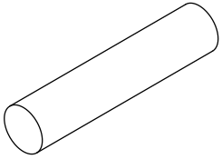
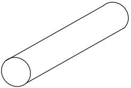
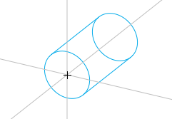
Except for a standard 30-30 isometric drawing, the Scaled option should probably be used for all other angles because of the difficulty of getting the views to be coordinated with each other. When the views are uncoordinated, you will get an odd-looking presentation if you try to draw a cylindrical rod.
WildTools 3D is embarrassed! When you have a poor choice of angles, WildTools 3D will be 'embarrassed' and the selected side of the 3D Cube will be purple, the angle text balloons will have a yellow warning background color, and the Scale checkbox will change to SCALE !! to encourage you to make a more sensible choice. If you persist and insist on not using scaling with odd angles, you may press the Shift key as you move the mouse to set both the X and Z angles at reasonably complimentary angles, but this is a flawed concept because this will work for a cylindrical rod along only one axis. You may also use the scroll wheel and two-finger gesture scrolling to change the angles and the action depends on whether the mouse location is over the cube or to the left or right of it. You may also use two-finger gesture rotation. Confused about the difference between an axonometric drawing and an axonometric project? Don't worry. It's much easier to understand the benefit. Up to now, we have all used '30-30 isometric' drawings because they were easy to draw, and other views produced a distorted appearance -- sometimes highly distorted. Axonometric Scaling means that you can easily use any view of the object. Once you have set these axes, all of the tools will 'know' that this is the way you want to draw. These settings are 'remembered' by WildTools 3D, and they are not stored in individual drawings.
These tools allow you to set the two axis angles by tracing a drawing. You just click and drag to draw a line.
You can tab into the Edit Window to set the angle.
This tool allows you to to draw the 'axle of the wheel' to set up WildTools 3D to match objects in the drawing. This only works to set the X and Z angles of the front and side view of the 3D Cube.
Selecting the Current View Plane
Click on a side of the cube control in the 3D Cube window. This is your primary method of changing the current view plane. As you will see, you will also find the cube control in the dialog boxes of many of the tools, and this changes the same setting. Whenever you use the cube control, you will be setting a 'global' variable, i.e. a setting that is shared by all of these tools. Thus, if you set it in one plane for one tool, you will set it that way for all tools which depend on the current view plane. |
![]()
Go back to WildTools