Jeff Morriss
![]()
Jeff Morriss |
|
|
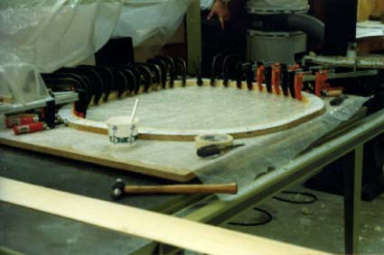
The fuselage forms were constructed by gluing white paper onto 0.75" particle board and then constructing the faired curves from the numbers furnished by Sequoia Aircraft. Once the curves were drawn, the board was bandsawed and drum sanded to the correct profile. The fuselage frames were constructed using stock supplied by Western Aircraft. The ends were previously scarfed at a 10:1 angle. Glue-up was done in a continuous spiral, one strip at a time using Aerolite glue. I clamped one strip at a time, partly because I lacked sufficient clamps to encompass the complete circumference, and partly because Aerolite has a very limited closed time. After the strip was completely glued up, it was removed and hand-planed to the correct thickness. A note to other builders: I have used two hand planes extensively: a block plane and a jack plane. For most smoothing operations, they work far better than anything else I have tried and have the advantage of producing shavings instead of sawdust. |
|
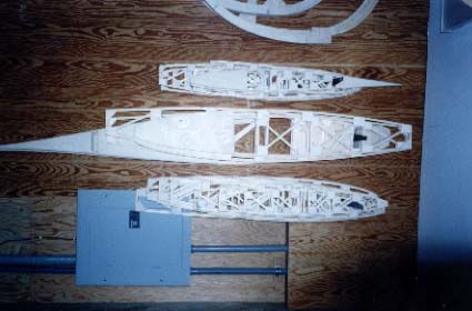
The wing and tail ribs were constructed directly from the drawings in the Falco plans in a method similar to that used for the fuselage frames. The major difference is that, since the ribs were drawn 1:1, it was possible to use a pounce wheel to directly transfer the dimensions onto paper glued to particle board. The board was then bandsawed to the correct shape. As with the fuselage frames, I used outside forms. Several builders have indicated they had problems with getting the capstrips to make a sharp curve at the leading edge. I avoided that problem by laminating the leading edge (only back to the spar) from two pieces of material and then placing the scarf joint over the location coinciding with the spar. When the rib was cut apart, the scarf joint was waste material. From the spar back the capstrip was made from a single piece of material. |
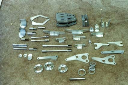
| The majority of wing components were fabricated from 2024-T3 alloy. The process was made easier because I have access to a lathe and a vertical mill. The rudder and elevator horns, as well as the flap and aileron hinges were initially hogged out of a 2"x2" billet to a "T" profile and then bored to achieve the necessary tolerances for the bearing seats. Other parts were fabricated from sheet, rounds and angle stock and riveted together as necessary. |
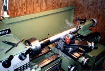
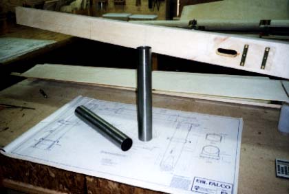
| This shows the tapering process for the main gear leg. This lathe has the ability to offset the tailstock and turn a taper, a fact that made the tapering process relatively easy. In order to mount the stock, it was first necessary to weld a plate on the end, center the piece with a steady rest, and then spot it with a centering drill so it could be mounted on a live center. |
| The finished result. The next step involved making the slits in the horizontal and vertical tubes to accommodate the strengthening web to which the oleo strut is mounted. This operation was done using a 7/64" stub endmill. |
![]()
|
|
Go back to Jeff Morriss