Jeff Morriss
![]()
Jeff Morriss |
|
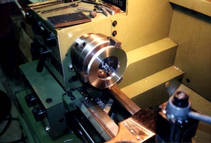
| Starting to make the crush plates that are mounted opposite the main landing gear bearing in the wing. In this case, I rough-cut the plate stock with a bandsaw, chucked with OD jaws and did the first roughing pass to produce a flat surface and a clean center diameter. Then I changed to ID jaws, chucked from the inside, finished the outside diameter and proceeded to cut the bolt head retention groove. The holes were drilled using a rotary table that made it possible to achieve an exact angular spacing and hole registration with the main bearings. |
|
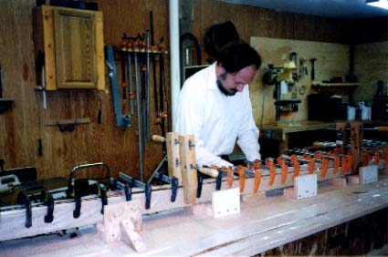
As with the fuselage frames, I elected to purchase pre-cut spruce from Western Aircraft and build the spars from plans. It was first necessary to build a 28 foot x 2 foot table. I found that the easiest way was to use prefabricated floor joists. They are remarkably straight and are available in the necessary lengths. I used short lengths of joists to build a rigid box assembly and then used 4x4 timbers as legs. Each leg had a bolt tapped into the bottom to permit leveling. A few quick passes with a jointer plane was sufficient to remove any irregularities on the top of the joists and yield a flat surface onto which 0.75" particle board was screwed. The final leveling was accomplished with a water level, and it was cross-checked with a laser to yield a surface flat to within ±0.5mm. The next step was laying out the WL and BL coordinates. This is where a laser proved its worth. Once the coordinates were laid out, then the dihedral could be marked and the clamping cleats located. I did notice after the entire glue-up process was complete that there was a tendency for the wing spar to take a softer turn at the point where the dihedral starts. Part of this problem was traced to the flexing of the table top surface and part to the movement of the cleat, even though it was securely screwed in place. If I were repeating this process, I would have doubled up the particle board or used a stronger material. Also, I would have built stronger cleats around the bend points. Glue-up was done with resorcinol and required every clamp that I, my neighbors, and a woodworker friend of mine owned. This photo shows a detail of the glue-up. The spar top and bottom were glued up separately, moving the cleats as necessary. The spar was protected during the glue-up by use of particle board cauls on both sides. |
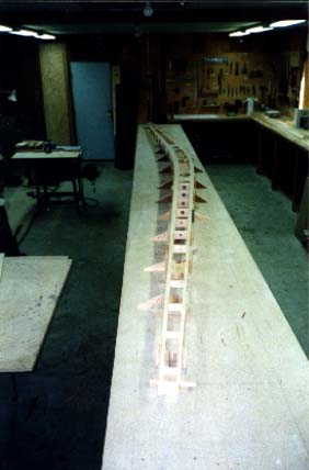
| This photo shows the glued-up spar with spacers before the plywood webs were added. Gluing up the top and bottom was done by using the top of the spar as the reference datum. That accounts for the location of cleats along the entire top of the spar. Aerolite was the glue of choice for this operation and all other operations except for the main spar laminations. |
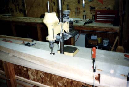
| After the plywood webs had been added, the next step was the drilling of the holes for the landing gear bearings. These holes had to be both accurate and square. For this operation, I unscrewed my bench-mounted drill press and mounted it directly onto the jig table. It was then a simple operation to square up the spar and complete the drilling operation. |
![]()
![]()
|
|
Go back to Jeff Morriss