Jeff Morriss
![]()
Jeff Morriss |
|
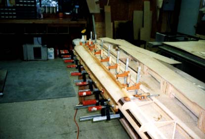
| The aileron/flap assembly was done using the spar table, as it provided a long, straight surface. I did find that holding the assembly in place did require some creative jig-building. As other builders have noted, getting the 2.0 mm leading edge skins to take the bend required patience, wet towels, and a hot iron. |
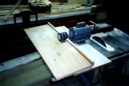
| I found a good scarfing machine to be an absolute necessity. This particular machine was simply a 1 HP motor mounted on a plywood base with a table set at 3.82°, or a 15/1 slope. A 3" sanding drum was attached to the motor shaft. Notice the small hole just to the right of the drum on the fence. There is a screw that permits a fine thickness adjustment by varying the distance from the drum to the table. Not shown, but added later, was an attachment to the shop dust collection system. |
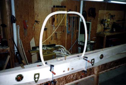
| This photo shows the frame #4 to main spar fitting. Everything had to be plumb and level. The spar was leveled using a water level to each tip, and the fuselage frame was plumbed in two directions. Only then did I think about gluing. |
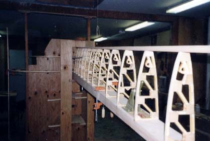
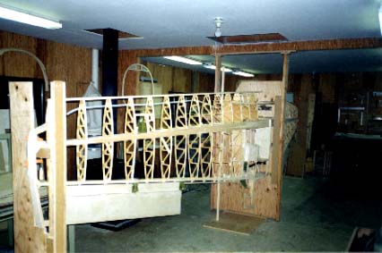
| The wing jigs were made according to the instructions supplied by Sequoia Aircraft. The only addition I made was the securing of the center frame to both the shop floor and ceiling. This proved to be very effective in minimizing unwanted movement. In this picture, the leading edge ribs are being test-fitted. |
| In this photo, the leading and trailing edge ribs have been glued and the process of float sanding started. One feature I did add to the exterior wing jigs was the ability to partially disassemble them, leaving a support on the trailing edge of the wing. This proved necessary in order to float sand out to the wing tips without interference. |
![]()
![]()
|
|
Go back to Jeff Morriss